Power system analysis
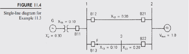
Figure shows a single-line diagram of a three-phase, 60-Hz synchronous generator, connected through a transformer and parallel transmission lines to an infinite bus. All reactances are given in perunit on a common system base. If the infinite bus receives 1.0 per unit real power at 0.95 p.f. lagging. If circuit breakers B13 and B22 are opened after three cycles and then reclosed when the power angle reaches 35°.
Assume ωpu(t) = 1.0 pu in the swing equation. Assume that the temporary fault has already self-extinguished when the breakers reclosed. Use the equal-area criterion to determine the maximum value of the power angle δ.
Homework Answers
Request Answer!
We need at least 10 more requests to produce the answer.
0 / 10 have requested this problem solution
The more requests, the faster the answer.
Figure 1 shows a single-line diagram of a three phase, 60-Hz, synchronous generator, connected th...
 Figure 1 shows a single-line diagram of a three phase, 60-Hz, synchronous generator, connected through a transformer and parallel transmission lines to an infinite bus. All reactances are given in per unit on a common system base. In steady state, the infinite bus receives 1.0 per unit real power at 0.95 power factor lagging. The generator in Figure 1 is initially operating in steady state, when circuit breaker B12 inadvertently opens. Use the equal area criterion to calculate the maximum...
XTR-0.10 B12 X12-0.20 B21 V= 1-0 x,-0.30 X23-0.20 B13 X13-0.10 B22 Fig. 1. Single-machine infinit...
 XTR-0.10 B12 X12-0.20 B21 V= 1-0 x,-0.30 X23-0.20 B13 X13-0.10 B22 Fig. 1. Single-machine infinite bus system (Simple system-I) 1. The synchronous generator in Fig.1 delivers 0.8 p.u. real power at 0.85 power factor leading at voltage at infinite bus (1.0 р.u. voltage). Determine a) The real and reactive power output of the generator b) The generator internal voltage c) An equation for the electrical power delivered by the generator as a function of 8. d) For a three-phase-to ground...
A 50 Hz, 250 MVA synchronous generator having inertia constant H=5 MJ/MVA is connected to an infinite bus through trans...
 A 50 Hz, 250 MVA synchronous generator having inertia constant H=5 MJ/MVA is connected to an infinite bus through transformer and transmission line as shown below. The transformer reactance is based on 500 MVA, while the other impedances are based on the generator MVA Infinite bus 1 2 3 XL 0.1 pu - oto G1 V= 1.0 pu X 0.1 pu Xd = 0.3 pu at 500 MVA The generator is delivering 0.8 of full load current at a power...
Question 2 A 60 Hz synchronous generator with Xd 0.2 pu transient reactance is connected to...
 Question 2 A 60 Hz synchronous generator with Xd 0.2 pu transient reactance is connected to an infinite us through a transformer and the transmisiones as shown in the Figure. All system reactances are marked on the diagram and are expressed on a common MVA base. The generator dies a power of Auto busbar 1. The magnitude of the generator's excitation voltage e'is 12 pu, and the infinite bus voltage is -1.00u. If a 3-phase fault occurs at the middle...
a) Calculate the generator internal voltage E’ and the initial generator power angle δ prior to...
 a) Calculate the generator internal voltage E’ and the initial
generator power angle δ prior to the fault.
b) Write the swing equation for the machine. What will be the
generator angle δ' at the instant when the fault is cleared after
0.1 s?
c)Determine whether the synchronous generator will remain stable
after the fault is cleared.
d) If the fault clearing is delayed, determine the critical
clearing angle and critical clearing time.
= A 50 Hz synchronous generator with...
a) Calculate the generator internal voltage E’ and the initial
generator power angle δ prior to the fault.
b) Write the swing equation for the machine. What will be the
generator angle δ' at the instant when the fault is cleared after
0.1 s?
c)Determine whether the synchronous generator will remain stable
after the fault is cleared.
d) If the fault clearing is delayed, determine the critical
clearing angle and critical clearing time.
= A 50 Hz synchronous generator with...
3. (30) A simple power system, shown below, is made up of a synchronous generatcr connected to a synchronous motor through a couple of transformers and a transmission line. The reactances of the...
 3. (30) A simple power system, shown below, is made up of a synchronous generatcr connected to a synchronous motor through a couple of transformers and a transmission line. The reactances of the different elements of the system are all given in pu as: Xsg-0.5 X of each transformer-10 % Xsm-0.5 X transmission line 0.3 The synchronous motor is connected to an infinite bus Hint: The great advantage of an infinite bus is that it always remains constant and our...
A synchronous generator is connected to an infinite bus via a transformer and a network of...
 A synchronous generator is connected to an infinite bus via a transformer and a network of transmission lines, as illustrated in Figure 1 below. Per unit reactances for all elements are shown to a common system base. The generator is delivering 1.1 per unit real power to the infinite bus, and the infinite bus voltage is regulated to 1.05 per unit. The excitation voltage of the synchronous generator is set to 1.30 per unit. The inertia constant of the generator...
A single line diagram of a power system is shown in Fig. 2. The system data with equipment ratings and assumed sequence reactances are given the following table. The neutrals of the generator and A-Y...
 A single line diagram of a power system is shown in Fig. 2. The system data with equipment ratings and assumed sequence reactances are given the following table. The neutrals of the generator and A-Y transformers are solidly grounded. The motor neutral is grounded through a reactance Xn 0.05 per unit on the motor base. Assume that Pre-fault voltage is takin as VF-1.0 ,0° per unit and Pre- fault load current and Δ-Y transformer phase shift are neglected In the...
PLEASE SOLVE THIS POWER / LOAD FLOW 07-Elec-B December 2016 Page 7 of 7 Problem 7...
 PLEASE SOLVE THIS POWER / LOAD FLOW
07-Elec-B December 2016 Page 7 of 7 Problem 7 Consider the system shown in the single-line diagram of Figure (5). Here, a 60-Hz synchronous generator having a transient reactance of 0.15 pu. is connected to an infinite bus through a transformer whose reactance is 0.1 p. u. and a double circuit transmission line with circuits having a reactance of 0.6 p.u each as indicated in the figurc. The generator delivers a real power...
PLEASE SOLVE THIS POWER / LOAD FLOW
07-Elec-B December 2016 Page 7 of 7 Problem 7 Consider the system shown in the single-line diagram of Figure (5). Here, a 60-Hz synchronous generator having a transient reactance of 0.15 pu. is connected to an infinite bus through a transformer whose reactance is 0.1 p. u. and a double circuit transmission line with circuits having a reactance of 0.6 p.u each as indicated in the figurc. The generator delivers a real power...
A synchronous generator with H = 3.5 is connected to an infinite bar through two lines...
A synchronous generator with H = 3.5 is connected to an infinite bar through two lines with reactances of 0.40 each. The generator internal voltage is 1.2 pu and the operating voltage of the infinite bar is 1.0 pu. A three phase fault occurs on one of the lines between the generator and the infinite bar. The fault is eliminated by opening one of the lines. Determine the critical angle and time to eliminate the fault without losing stability.
 Figure 1 shows a single-line diagram of a three phase, 60-Hz, synchronous generator, connected through a transformer and parallel transmission lines to an infinite bus. All reactances are given in per unit on a common system base. In steady state, the infinite bus receives 1.0 per unit real power at 0.95 power factor lagging. The generator in Figure 1 is initially operating in steady state, when circuit breaker B12 inadvertently opens. Use the equal area criterion to calculate the maximum...
 XTR-0.10 B12 X12-0.20 B21 V= 1-0 x,-0.30 X23-0.20 B13 X13-0.10 B22 Fig. 1. Single-machine infinite bus system (Simple system-I) 1. The synchronous generator in Fig.1 delivers 0.8 p.u. real power at 0.85 power factor leading at voltage at infinite bus (1.0 р.u. voltage). Determine a) The real and reactive power output of the generator b) The generator internal voltage c) An equation for the electrical power delivered by the generator as a function of 8. d) For a three-phase-to ground...
 A 50 Hz, 250 MVA synchronous generator having inertia constant H=5 MJ/MVA is connected to an infinite bus through transformer and transmission line as shown below. The transformer reactance is based on 500 MVA, while the other impedances are based on the generator MVA Infinite bus 1 2 3 XL 0.1 pu - oto G1 V= 1.0 pu X 0.1 pu Xd = 0.3 pu at 500 MVA The generator is delivering 0.8 of full load current at a power...
 Question 2 A 60 Hz synchronous generator with Xd 0.2 pu transient reactance is connected to an infinite us through a transformer and the transmisiones as shown in the Figure. All system reactances are marked on the diagram and are expressed on a common MVA base. The generator dies a power of Auto busbar 1. The magnitude of the generator's excitation voltage e'is 12 pu, and the infinite bus voltage is -1.00u. If a 3-phase fault occurs at the middle...
 a) Calculate the generator internal voltage E’ and the initial
generator power angle δ prior to the fault.
b) Write the swing equation for the machine. What will be the
generator angle δ' at the instant when the fault is cleared after
0.1 s?
c)Determine whether the synchronous generator will remain stable
after the fault is cleared.
d) If the fault clearing is delayed, determine the critical
clearing angle and critical clearing time.
= A 50 Hz synchronous generator with...
a) Calculate the generator internal voltage E’ and the initial
generator power angle δ prior to the fault.
b) Write the swing equation for the machine. What will be the
generator angle δ' at the instant when the fault is cleared after
0.1 s?
c)Determine whether the synchronous generator will remain stable
after the fault is cleared.
d) If the fault clearing is delayed, determine the critical
clearing angle and critical clearing time.
= A 50 Hz synchronous generator with...
 3. (30) A simple power system, shown below, is made up of a synchronous generatcr connected to a synchronous motor through a couple of transformers and a transmission line. The reactances of the different elements of the system are all given in pu as: Xsg-0.5 X of each transformer-10 % Xsm-0.5 X transmission line 0.3 The synchronous motor is connected to an infinite bus Hint: The great advantage of an infinite bus is that it always remains constant and our...
 A synchronous generator is connected to an infinite bus via a transformer and a network of transmission lines, as illustrated in Figure 1 below. Per unit reactances for all elements are shown to a common system base. The generator is delivering 1.1 per unit real power to the infinite bus, and the infinite bus voltage is regulated to 1.05 per unit. The excitation voltage of the synchronous generator is set to 1.30 per unit. The inertia constant of the generator...
 A single line diagram of a power system is shown in Fig. 2. The system data with equipment ratings and assumed sequence reactances are given the following table. The neutrals of the generator and A-Y transformers are solidly grounded. The motor neutral is grounded through a reactance Xn 0.05 per unit on the motor base. Assume that Pre-fault voltage is takin as VF-1.0 ,0° per unit and Pre- fault load current and Δ-Y transformer phase shift are neglected In the...
 PLEASE SOLVE THIS POWER / LOAD FLOW
07-Elec-B December 2016 Page 7 of 7 Problem 7 Consider the system shown in the single-line diagram of Figure (5). Here, a 60-Hz synchronous generator having a transient reactance of 0.15 pu. is connected to an infinite bus through a transformer whose reactance is 0.1 p. u. and a double circuit transmission line with circuits having a reactance of 0.6 p.u each as indicated in the figurc. The generator delivers a real power...
PLEASE SOLVE THIS POWER / LOAD FLOW
07-Elec-B December 2016 Page 7 of 7 Problem 7 Consider the system shown in the single-line diagram of Figure (5). Here, a 60-Hz synchronous generator having a transient reactance of 0.15 pu. is connected to an infinite bus through a transformer whose reactance is 0.1 p. u. and a double circuit transmission line with circuits having a reactance of 0.6 p.u each as indicated in the figurc. The generator delivers a real power...
Most questions answered within 3 hours.
-
Humans have used horses for transportation for millions of
years. Therefore, they will use horses for...
asked 1 hour ago -
The following are the Jensen Corporation's unit costs of making
and selling an item at a...
asked 1 hour ago -
Does direct Medicare reimbursement of Advanced practice nurses
increase access to their services?
asked 2 hours ago -
List and explain why a company would choose to use a
published
compensation survey vs. creating...
asked 2 hours ago -
A discrete random variable X can take values from 1 to 10. Find
the variance of...
asked 3 hours ago -
The primary financial goal of a corporation is to maximize:
shareholders wealth.
earnings per share.
stock...
asked 3 hours ago -
determine whether the vectors u=(1,2,3,), v=(-2,1,0) and
w=(1,0,1) are linearly dependent or independent.
asked 3 hours ago -
python
Define a function called print_values which takes a dictionary
object as a parameter. The function...
asked 4 hours ago -
In Chapter 1 you created a program named Triangle in
which you displayed a seven-line triangle...
asked 4 hours ago -
Research question: What are the differences between separately
stated and non separately stated transactions in an...
asked 4 hours ago -
By using Arduino write a code that connects two LEDs to two
push-buttons. Each button controls...
asked 5 hours ago -
Bank of America has bonds that pay a coupon interest rate of 5.5
percent and mature...
asked 6 hours ago