
Homework Answers

Add Answer to:
Be sure that you have enough knowledge and right answer with step by step solution and...
PLEASE SO PART C, THANK YOU WILL RATE. A single-phase transformer with a 5:1 turns ratio...
 PLEASE SO PART C, THANK YOU WILL RATE.
A single-phase transformer with a 5:1 turns ratio is connected to a 600 V voltage source on the primary side, and a 5 Ω resistor on the secondary. A current of 22 amps of current is measured to flow through the 5 Ω resistor on the secondary side. The real power flowing into the transformer primary is measured at 2500 W. You can neglect Lm and Rc (the magnetizing inductance and core...
PLEASE SO PART C, THANK YOU WILL RATE.
A single-phase transformer with a 5:1 turns ratio is connected to a 600 V voltage source on the primary side, and a 5 Ω resistor on the secondary. A current of 22 amps of current is measured to flow through the 5 Ω resistor on the secondary side. The real power flowing into the transformer primary is measured at 2500 W. You can neglect Lm and Rc (the magnetizing inductance and core...
Can you make sure solution has the answer that is stated above on the right
 Can you make sure solution has the answer that is stated above
on the right
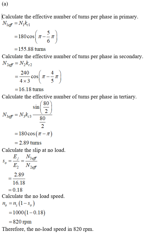
3. A 3ф, 460 V, 60 Hz, 50 hp, 1180 rpm induction motor has the following parameters: Ts-0.191 ohms, -0.0707 ohms, Lis 2 mH, (stator leakage inductance) Lr 2 mH (rotor leakage inductance, referred to stator) Lm 44.8 mH Determine the values of the rated stator current Is and rated motor torque Te using the exact T equivalent circuit. Hint: a motor reactance X-jaeL Answer:...
Can you make sure solution has the answer that is stated above
on the right
3. A 3ф, 460 V, 60 Hz, 50 hp, 1180 rpm induction motor has the following parameters: Ts-0.191 ohms, -0.0707 ohms, Lis 2 mH, (stator leakage inductance) Lr 2 mH (rotor leakage inductance, referred to stator) Lm 44.8 mH Determine the values of the rated stator current Is and rated motor torque Te using the exact T equivalent circuit. Hint: a motor reactance X-jaeL Answer:...
Electrical Instrumentation and Measurements
 1. (a) i. Briefly explain the three (3) main functions of instruments and give examples each. ii. Explain loading effects in a measurement system.(b) A Maxwell bridge in Fig 1 below is used to measure an inductive impedance. The bridge constants at balance are:R1 = 235 kΩ, C1 = 0.012 µF, R2 = 2.5 kΩ, R3 = 50 kΩFind the series equivalent of the unknown impedance. 2. (a) The power input to a 3-phase induction...
Please answer all the questions, thank you! It is a important homework for me! I will...
 Please answer all the questions, thank you! It is a important
homework for me! I will like you answer if correct!
For the questions on this page, assume that that an induction motor is rated to deliver 10kW (approximately 13.3HP} when operated at 240VRMS 60Hz. The motor has a lagging power factor of 0.8. The building electrical service only supplies 208VRMs, so the motor can not be connected directly to the electric service. An ideal transformer is used to create...
Please answer all the questions, thank you! It is a important
homework for me! I will like you answer if correct!
For the questions on this page, assume that that an induction motor is rated to deliver 10kW (approximately 13.3HP} when operated at 240VRMS 60Hz. The motor has a lagging power factor of 0.8. The building electrical service only supplies 208VRMs, so the motor can not be connected directly to the electric service. An ideal transformer is used to create...
Accuracy is important. Do not round intermediates and check the answer range to make sure you...
 Accuracy is important. Do not round intermediates and check the
answer range to make sure you are correct.
Values:
[01] 2.08 [02]
68.47 [03] 0.239 [04] 1173.7 [05] 1403. [06] 53.8
THE CORRECT ANSWERS WILL BE IN THE FOLLOWING RANGES:
8-1a. 140, 220 Hz
8-1b. 40:0, 62:0 mA
8-2a. 70:0, 99:0 V
8-2b. 140:0, 160:0 V
8-2c. 60:0, 99:0 V
8-2d. 60:0, 90:0 V
8-3a. 40:0; 99:0 pF
8-3b. 100; 400 mV
8-3c. 1:00; 3:00 mV
8-4a. 100; 150 V...
Accuracy is important. Do not round intermediates and check the
answer range to make sure you are correct.
Values:
[01] 2.08 [02]
68.47 [03] 0.239 [04] 1173.7 [05] 1403. [06] 53.8
THE CORRECT ANSWERS WILL BE IN THE FOLLOWING RANGES:
8-1a. 140, 220 Hz
8-1b. 40:0, 62:0 mA
8-2a. 70:0, 99:0 V
8-2b. 140:0, 160:0 V
8-2c. 60:0, 99:0 V
8-2d. 60:0, 90:0 V
8-3a. 40:0; 99:0 pF
8-3b. 100; 400 mV
8-3c. 1:00; 3:00 mV
8-4a. 100; 150 V...
ll capace, expressed in oks. They 9. The opposition offered to the non offered to the...
 ll capace, expressed in oks. They 9. The opposition offered to the non offered to the flow of a C alensis XE. 1. Inductive Reactance 2. Capacitive Reactance 3. Impedance 4. Resistance 10. The opposition offered to the The opposition offered to the flow of an alteratine curenty inductance, expressed in ons. The symbol for characteristic is XL. 1. Inductive Reactance 2. Capacitive Reactance 3. Impedance when a voltage 11. What is the basic unit of capacitance? Example: A capacitor...
solve no: 3.14 , 3.16, 3.19 please show each step and solve for beginners 120 Power...
 solve no: 3.14 , 3.16, 3.19
please show each step and solve for beginners
120 Power System Analysis 3.12. A single-phase system similar to that shown in Figure 3.11 has two transformers A-B a B-C connected by a line B feeding a load at the receiving end C. The ratings and parame ter values of the components are 500 V/1.5 kV, 9.6 kVA. leakage reactance 5 % 1.2 kV/120 V, 7.2 kVA, leakage reactance 4 % series impedance (0.5 +...
solve no: 3.14 , 3.16, 3.19
please show each step and solve for beginners
120 Power System Analysis 3.12. A single-phase system similar to that shown in Figure 3.11 has two transformers A-B a B-C connected by a line B feeding a load at the receiving end C. The ratings and parame ter values of the components are 500 V/1.5 kV, 9.6 kVA. leakage reactance 5 % 1.2 kV/120 V, 7.2 kVA, leakage reactance 4 % series impedance (0.5 +...
 PLEASE SO PART C, THANK YOU WILL RATE.
A single-phase transformer with a 5:1 turns ratio is connected to a 600 V voltage source on the primary side, and a 5 Ω resistor on the secondary. A current of 22 amps of current is measured to flow through the 5 Ω resistor on the secondary side. The real power flowing into the transformer primary is measured at 2500 W. You can neglect Lm and Rc (the magnetizing inductance and core...
PLEASE SO PART C, THANK YOU WILL RATE.
A single-phase transformer with a 5:1 turns ratio is connected to a 600 V voltage source on the primary side, and a 5 Ω resistor on the secondary. A current of 22 amps of current is measured to flow through the 5 Ω resistor on the secondary side. The real power flowing into the transformer primary is measured at 2500 W. You can neglect Lm and Rc (the magnetizing inductance and core...
 Can you make sure solution has the answer that is stated above
on the right
3. A 3ф, 460 V, 60 Hz, 50 hp, 1180 rpm induction motor has the following parameters: Ts-0.191 ohms, -0.0707 ohms, Lis 2 mH, (stator leakage inductance) Lr 2 mH (rotor leakage inductance, referred to stator) Lm 44.8 mH Determine the values of the rated stator current Is and rated motor torque Te using the exact T equivalent circuit. Hint: a motor reactance X-jaeL Answer:...
Can you make sure solution has the answer that is stated above
on the right
3. A 3ф, 460 V, 60 Hz, 50 hp, 1180 rpm induction motor has the following parameters: Ts-0.191 ohms, -0.0707 ohms, Lis 2 mH, (stator leakage inductance) Lr 2 mH (rotor leakage inductance, referred to stator) Lm 44.8 mH Determine the values of the rated stator current Is and rated motor torque Te using the exact T equivalent circuit. Hint: a motor reactance X-jaeL Answer:...
 Please answer all the questions, thank you! It is a important
homework for me! I will like you answer if correct!
For the questions on this page, assume that that an induction motor is rated to deliver 10kW (approximately 13.3HP} when operated at 240VRMS 60Hz. The motor has a lagging power factor of 0.8. The building electrical service only supplies 208VRMs, so the motor can not be connected directly to the electric service. An ideal transformer is used to create...
Please answer all the questions, thank you! It is a important
homework for me! I will like you answer if correct!
For the questions on this page, assume that that an induction motor is rated to deliver 10kW (approximately 13.3HP} when operated at 240VRMS 60Hz. The motor has a lagging power factor of 0.8. The building electrical service only supplies 208VRMs, so the motor can not be connected directly to the electric service. An ideal transformer is used to create...
 Accuracy is important. Do not round intermediates and check the
answer range to make sure you are correct.
Values:
[01] 2.08 [02]
68.47 [03] 0.239 [04] 1173.7 [05] 1403. [06] 53.8
THE CORRECT ANSWERS WILL BE IN THE FOLLOWING RANGES:
8-1a. 140, 220 Hz
8-1b. 40:0, 62:0 mA
8-2a. 70:0, 99:0 V
8-2b. 140:0, 160:0 V
8-2c. 60:0, 99:0 V
8-2d. 60:0, 90:0 V
8-3a. 40:0; 99:0 pF
8-3b. 100; 400 mV
8-3c. 1:00; 3:00 mV
8-4a. 100; 150 V...
Accuracy is important. Do not round intermediates and check the
answer range to make sure you are correct.
Values:
[01] 2.08 [02]
68.47 [03] 0.239 [04] 1173.7 [05] 1403. [06] 53.8
THE CORRECT ANSWERS WILL BE IN THE FOLLOWING RANGES:
8-1a. 140, 220 Hz
8-1b. 40:0, 62:0 mA
8-2a. 70:0, 99:0 V
8-2b. 140:0, 160:0 V
8-2c. 60:0, 99:0 V
8-2d. 60:0, 90:0 V
8-3a. 40:0; 99:0 pF
8-3b. 100; 400 mV
8-3c. 1:00; 3:00 mV
8-4a. 100; 150 V...
 ll capace, expressed in oks. They 9. The opposition offered to the non offered to the flow of a C alensis XE. 1. Inductive Reactance 2. Capacitive Reactance 3. Impedance 4. Resistance 10. The opposition offered to the The opposition offered to the flow of an alteratine curenty inductance, expressed in ons. The symbol for characteristic is XL. 1. Inductive Reactance 2. Capacitive Reactance 3. Impedance when a voltage 11. What is the basic unit of capacitance? Example: A capacitor...
 solve no: 3.14 , 3.16, 3.19
please show each step and solve for beginners
120 Power System Analysis 3.12. A single-phase system similar to that shown in Figure 3.11 has two transformers A-B a B-C connected by a line B feeding a load at the receiving end C. The ratings and parame ter values of the components are 500 V/1.5 kV, 9.6 kVA. leakage reactance 5 % 1.2 kV/120 V, 7.2 kVA, leakage reactance 4 % series impedance (0.5 +...
solve no: 3.14 , 3.16, 3.19
please show each step and solve for beginners
120 Power System Analysis 3.12. A single-phase system similar to that shown in Figure 3.11 has two transformers A-B a B-C connected by a line B feeding a load at the receiving end C. The ratings and parame ter values of the components are 500 V/1.5 kV, 9.6 kVA. leakage reactance 5 % 1.2 kV/120 V, 7.2 kVA, leakage reactance 4 % series impedance (0.5 +...
Most questions answered within 3 hours.
-
A coach uses a new technique to train gymnasts. Seven
gymnasts were randomly selected and their...
asked 1 hour ago -
While rotating the tires on your car you notice a rock [mass =
0.1 Kg] stuck...
asked 3 hours ago -
Using MARS simulator, write MIPS programs according to
the following scenarios: Receive a positive integer number...
asked 5 hours ago -
An object in front of a concave mirror has a real image that is
11.5 cm...
asked 5 hours ago -
Consider the reaction, C3 H8 + O2 --> CO2 + H2O. How many
moles of O2...
asked 7 hours ago -
You and your opponent both roll a fair die. If you both roll the
same number,...
asked 7 hours ago -
In a study of the accuracy of fast food drive-through orders,
Restaurant A had 257 accurate...
asked 7 hours ago -
Identify and describe in detail the four categories of
institutions that could be included in a...
asked 7 hours ago -
In python
class Customer:
def __init__(self, customer_id, last_name, first_name, phone_number, address):
self._customer_id = int(customer_id)
self._last_name =...
asked 7 hours ago -
What is an example of a limitation in implementing a new
ERP system and how it...
asked 7 hours ago -
In a section of 9.7cm of an artery with a radius of 2.6mm there
is a...
asked 7 hours ago -
the two carboxylic acid groups of aspartic acid have different
acidities with pKa values of 2.1...
asked 7 hours ago