
Homework Answers

Add Answer to:
please help me as soon as possible. thanks
100 mH + + 560 0 100 V...
just do question 26 and 30 and show all your work (a) Select R so that 26. For the cincuit of Fig. 943,.40 30u-) m v...
 just do question 26 and 30 and show all your work
(a) Select R so that 26. For the cincuit of Fig. 943,.40 30u-) m v(0+) 6 V. (b) Compute (2 ms). (c) Determine the settling time of the capacitor voltage. (d) Is the inductor current settling time the same as your answer to part (c)? 27. The current source in Fig. 9.43 is id) = 101(1-1) μ A. (a) Select Ri such that iLO")-2 μΑ. Compute L at t-500...
just do question 26 and 30 and show all your work
(a) Select R so that 26. For the cincuit of Fig. 943,.40 30u-) m v(0+) 6 V. (b) Compute (2 ms). (c) Determine the settling time of the capacitor voltage. (d) Is the inductor current settling time the same as your answer to part (c)? 27. The current source in Fig. 9.43 is id) = 101(1-1) μ A. (a) Select Ri such that iLO")-2 μΑ. Compute L at t-500...
Sponse Question 8 800 22 640 mH =0 90 15 V TUF After the switch is...
 Sponse Question 8 800 22 640 mH =0 90 15 V TUF After the switch is thrown at r=0, will the circuit behave in an overdamped, critically damped, or underdag Critically damped Underdamped. O Overdamped. Moving to another question will save this response. ere to search
Determine if overdamped,underdamped, or critically damped For the circuit shown below, Vs-200V, R-30, R.-50. C -0.125pF...
 Determine if overdamped,underdamped, or critically damped
For the circuit shown below, Vs-200V, R-30, R.-50. C -0.125pF and L-SmH. Find (a) the initial voltage across the capacitor 20. (b) the initial current through the inductor, lu(0). (e) the damping coefficient and resonant frequency . (d) the initial condition dvede , (e) the voltage across the capacitor (t) for the initial condition diu/dt , and the current through the inductor lu(t) for p R2 Voc
Determine if overdamped,underdamped, or critically damped
For the circuit shown below, Vs-200V, R-30, R.-50. C -0.125pF and L-SmH. Find (a) the initial voltage across the capacitor 20. (b) the initial current through the inductor, lu(0). (e) the damping coefficient and resonant frequency . (d) the initial condition dvede , (e) the voltage across the capacitor (t) for the initial condition diu/dt , and the current through the inductor lu(t) for p R2 Voc
Function Generatr Inductor Model Ra R, Figure 1 Series RLC Circuit Preliminary This laboratory wi...
 Function Generatr Inductor Model Ra R, Figure 1 Series RLC Circuit Preliminary This laboratory will demonstrate how varying resistance changes the natural response of a series RLC circuit (Fig. 1). The function generator is modeled as an ideal voltage source v(t) 5 u() V in series with source resistance Rs-50Q. After measurements using an LCR meter, the inductor is modeled as an ideal L 90 mH inductor in series with resistance RL-20Q. The capacitance is C-0.22 μF. 1) Calculate the...
Problem 5: Consider the circuit shown in the figure below in which the initial inductor current...
 Problem 5: Consider the circuit shown in the figure below in which the initial inductor current and capacitor voltage are both zero. (a) Write the differential equation for vc(t). (b) Find the particular solution. (c) Is this circuit overdamped, critically damped, or underdamped? 4 0 i(t) vc()
Engineering circuit analysis by Hayt 8th edition question 27 and figure 9.43 I think 10u(1-t) means 10 (for t<1)...
 Engineering circuit analysis by Hayt
8th edition
question 27 and figure 9.43
I think 10u(1-t) means 10 (for t<1) and 0
(for t>1)
then, I can't remove this current source because it
continuously make 10micro A
(at t=500ms, t=1.002ms)
I don't know what's wrong now..
366 26. For the circuit of Fig. 9,43, 1 30-) mA. (a) Select R, so th O)6 V (b) Compute e2 ms). (c) Determine the settling, time of t capacitor voltage. (d) Is the inductor...
Engineering circuit analysis by Hayt
8th edition
question 27 and figure 9.43
I think 10u(1-t) means 10 (for t<1) and 0
(for t>1)
then, I can't remove this current source because it
continuously make 10micro A
(at t=500ms, t=1.002ms)
I don't know what's wrong now..
366 26. For the circuit of Fig. 9,43, 1 30-) mA. (a) Select R, so th O)6 V (b) Compute e2 ms). (c) Determine the settling, time of t capacitor voltage. (d) Is the inductor...
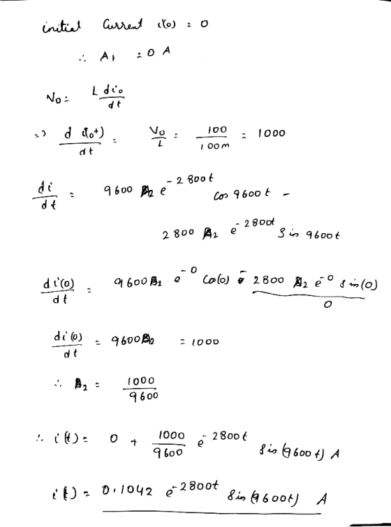
Problem 5 (20 points) No energy is stored in the 100 mH inductor or the 0.4...
 Problem 5 (20 points) No energy is stored in the 100 mH inductor or the 0.4 LF capacitor when the switch in the circuit shown in figure below is closed. 0.1 H -O 2800 0.4 F 50 V uc Fig. 5 a) Find the values of a and co b) What is the type of circuit response for t>0? c)What is the initial voltage across the capacitor at t=0- and at t=0+? d) Find an expression for the current through...
R: 1 , 5.1 C .022 μF L: 47 mH WA v; () Fig. 4 -...
 R: 1 , 5.1
C .022 μF
L: 47 mH
WA v; () Fig. 4 - RLC circuit powered by the function generator set to a square wave The inductor voltage can be solved by first determining the circuit current, then by differentiating the current using the following equation. For the details of the RLC circuit theory please refer to the lecture notes. ve = Leate 1 = 0 on R C off VZORL Fig. 5 - Model of the...
R: 1 , 5.1
C .022 μF
L: 47 mH
WA v; () Fig. 4 - RLC circuit powered by the function generator set to a square wave The inductor voltage can be solved by first determining the circuit current, then by differentiating the current using the following equation. For the details of the RLC circuit theory please refer to the lecture notes. ve = Leate 1 = 0 on R C off VZORL Fig. 5 - Model of the...
The answer key says Underdamped, but i do not understand why. Question 10 In the circuit below, the inductor current, iz(), for t2 0 is known to be, -10t 1012 ve(t)) Vc(t) Find the response curve tha...
 The answer key says Underdamped, but i do not understand
why.
Question 10 In the circuit below, the inductor current, iz(), for t2 0 is known to be, -10t 1012 ve(t)) Vc(t) Find the response curve that best represents the inductor current above iL(t) iL(t) (2) Underdamped (1) Undamped it t) i(t) (4) Overdamped (3) Critically damped (5) None of the above
Question 10 In the circuit below, the inductor current, iz(), for t2 0 is known to be, -10t...
The answer key says Underdamped, but i do not understand
why.
Question 10 In the circuit below, the inductor current, iz(), for t2 0 is known to be, -10t 1012 ve(t)) Vc(t) Find the response curve that best represents the inductor current above iL(t) iL(t) (2) Underdamped (1) Undamped it t) i(t) (4) Overdamped (3) Critically damped (5) None of the above
Question 10 In the circuit below, the inductor current, iz(), for t2 0 is known to be, -10t...
Figure 1 shows a circuit after some switch-flipping and is now at time t = 0....
 Figure 1 shows a circuit after some switch-flipping and is now at time t = 0. It contains a capacitor that was charged to v.(0") = 75 V and an inductor that was charged to i (0°) = 3 A. 10) Is this circuit overdamped, underdamped, or critically damped [2 points A) Is this circuit displaying a natural or step response? (2 points) Solve for y(t) fort > 0 [8 points) +35w 13.230.išao Ous. "
 just do question 26 and 30 and show all your work
(a) Select R so that 26. For the cincuit of Fig. 943,.40 30u-) m v(0+) 6 V. (b) Compute (2 ms). (c) Determine the settling time of the capacitor voltage. (d) Is the inductor current settling time the same as your answer to part (c)? 27. The current source in Fig. 9.43 is id) = 101(1-1) μ A. (a) Select Ri such that iLO")-2 μΑ. Compute L at t-500...
just do question 26 and 30 and show all your work
(a) Select R so that 26. For the cincuit of Fig. 943,.40 30u-) m v(0+) 6 V. (b) Compute (2 ms). (c) Determine the settling time of the capacitor voltage. (d) Is the inductor current settling time the same as your answer to part (c)? 27. The current source in Fig. 9.43 is id) = 101(1-1) μ A. (a) Select Ri such that iLO")-2 μΑ. Compute L at t-500...
 Sponse Question 8 800 22 640 mH =0 90 15 V TUF After the switch is thrown at r=0, will the circuit behave in an overdamped, critically damped, or underdag Critically damped Underdamped. O Overdamped. Moving to another question will save this response. ere to search
 Determine if overdamped,underdamped, or critically damped
For the circuit shown below, Vs-200V, R-30, R.-50. C -0.125pF and L-SmH. Find (a) the initial voltage across the capacitor 20. (b) the initial current through the inductor, lu(0). (e) the damping coefficient and resonant frequency . (d) the initial condition dvede , (e) the voltage across the capacitor (t) for the initial condition diu/dt , and the current through the inductor lu(t) for p R2 Voc
Determine if overdamped,underdamped, or critically damped
For the circuit shown below, Vs-200V, R-30, R.-50. C -0.125pF and L-SmH. Find (a) the initial voltage across the capacitor 20. (b) the initial current through the inductor, lu(0). (e) the damping coefficient and resonant frequency . (d) the initial condition dvede , (e) the voltage across the capacitor (t) for the initial condition diu/dt , and the current through the inductor lu(t) for p R2 Voc
 Function Generatr Inductor Model Ra R, Figure 1 Series RLC Circuit Preliminary This laboratory will demonstrate how varying resistance changes the natural response of a series RLC circuit (Fig. 1). The function generator is modeled as an ideal voltage source v(t) 5 u() V in series with source resistance Rs-50Q. After measurements using an LCR meter, the inductor is modeled as an ideal L 90 mH inductor in series with resistance RL-20Q. The capacitance is C-0.22 μF. 1) Calculate the...
 Problem 5: Consider the circuit shown in the figure below in which the initial inductor current and capacitor voltage are both zero. (a) Write the differential equation for vc(t). (b) Find the particular solution. (c) Is this circuit overdamped, critically damped, or underdamped? 4 0 i(t) vc()
 Engineering circuit analysis by Hayt
8th edition
question 27 and figure 9.43
I think 10u(1-t) means 10 (for t<1) and 0
(for t>1)
then, I can't remove this current source because it
continuously make 10micro A
(at t=500ms, t=1.002ms)
I don't know what's wrong now..
366 26. For the circuit of Fig. 9,43, 1 30-) mA. (a) Select R, so th O)6 V (b) Compute e2 ms). (c) Determine the settling, time of t capacitor voltage. (d) Is the inductor...
Engineering circuit analysis by Hayt
8th edition
question 27 and figure 9.43
I think 10u(1-t) means 10 (for t<1) and 0
(for t>1)
then, I can't remove this current source because it
continuously make 10micro A
(at t=500ms, t=1.002ms)
I don't know what's wrong now..
366 26. For the circuit of Fig. 9,43, 1 30-) mA. (a) Select R, so th O)6 V (b) Compute e2 ms). (c) Determine the settling, time of t capacitor voltage. (d) Is the inductor...
 Problem 5 (20 points) No energy is stored in the 100 mH inductor or the 0.4 LF capacitor when the switch in the circuit shown in figure below is closed. 0.1 H -O 2800 0.4 F 50 V uc Fig. 5 a) Find the values of a and co b) What is the type of circuit response for t>0? c)What is the initial voltage across the capacitor at t=0- and at t=0+? d) Find an expression for the current through...
 R: 1 , 5.1
C .022 μF
L: 47 mH
WA v; () Fig. 4 - RLC circuit powered by the function generator set to a square wave The inductor voltage can be solved by first determining the circuit current, then by differentiating the current using the following equation. For the details of the RLC circuit theory please refer to the lecture notes. ve = Leate 1 = 0 on R C off VZORL Fig. 5 - Model of the...
R: 1 , 5.1
C .022 μF
L: 47 mH
WA v; () Fig. 4 - RLC circuit powered by the function generator set to a square wave The inductor voltage can be solved by first determining the circuit current, then by differentiating the current using the following equation. For the details of the RLC circuit theory please refer to the lecture notes. ve = Leate 1 = 0 on R C off VZORL Fig. 5 - Model of the...
 The answer key says Underdamped, but i do not understand
why.
Question 10 In the circuit below, the inductor current, iz(), for t2 0 is known to be, -10t 1012 ve(t)) Vc(t) Find the response curve that best represents the inductor current above iL(t) iL(t) (2) Underdamped (1) Undamped it t) i(t) (4) Overdamped (3) Critically damped (5) None of the above
Question 10 In the circuit below, the inductor current, iz(), for t2 0 is known to be, -10t...
The answer key says Underdamped, but i do not understand
why.
Question 10 In the circuit below, the inductor current, iz(), for t2 0 is known to be, -10t 1012 ve(t)) Vc(t) Find the response curve that best represents the inductor current above iL(t) iL(t) (2) Underdamped (1) Undamped it t) i(t) (4) Overdamped (3) Critically damped (5) None of the above
Question 10 In the circuit below, the inductor current, iz(), for t2 0 is known to be, -10t...
 Figure 1 shows a circuit after some switch-flipping and is now at time t = 0. It contains a capacitor that was charged to v.(0") = 75 V and an inductor that was charged to i (0°) = 3 A. 10) Is this circuit overdamped, underdamped, or critically damped [2 points A) Is this circuit displaying a natural or step response? (2 points) Solve for y(t) fort > 0 [8 points) +35w 13.230.išao Ous. "
Most questions answered within 3 hours.
-
ECO
2013 &
asked 22 seconds from now -
Insight refers to:
a.
Adaptive decision-making
b.
Credibility and trustworthness
c.
Understanding of one's problems
d....
asked 5 minutes ago -
Explain the differences between rights and permissions within
Windows. Define the principle of least privilege and...
asked 13 minutes ago -
A solid, frictionless cylindrical reel of mass M=5.00kg and
radius R=0.55m is used to draw water...
asked 15 minutes ago -
how do radio waves get emitted from Jupiter?
- do they come from radiation from planet...
asked 16 minutes ago -
The test statistic used in the F test for the equality of two
variances is calculated...
asked 27 minutes ago -
How does neutralisation of IL-6 trans-signaling affect the
autoimmune disease and inflammation? What if the trans-signaling...
asked 17 minutes ago -
f an allele is 'fixed' in a population, what is its
frequency?
0.50
0.75
0.25
0...
asked 32 minutes ago -
Do we have a duty of national loyalty in business? What is the
major argument in...
asked 32 minutes ago -
compare the international treatment of segment reporting to the
us gaap treatment
asked 28 minutes ago -
A statistics student finds herself struggling with a newspaper
article stating that only eighteen percent of...
asked 1 hour ago -
People with beriberi, a disease caused by a thiamin deficiency,
have elevated levels of blood pyruvate...
asked 49 minutes ago