
Homework Answers


Add Answer to:
Problem 5 (20 points) No energy is stored in the 100 mH inductor or the 0.4...
2. Charge-up response of series RLC circuit. No energy is stored in the 0.1H inductor or...
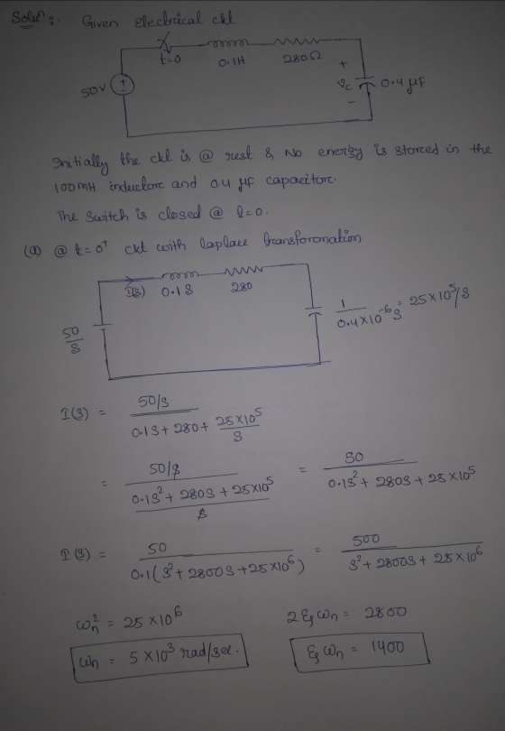
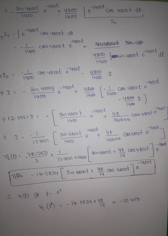
 2. Charge-up response of series RLC circuit. No energy is stored in the 0.1H inductor or the 0.4uF capacitor before the switch in the circuit shown in the figure below is closed. Find S2 Key= A 2800 1. 0.4uF - 3. Discharge response of series RLC circuit. The circuit had been in steady state prior to moving the switch at t=0. Find = Key = Space Key C1 0.44F For both circuits: a) Is the response underdamped, overdamped, or critically...
Consider the circuit shown in Fig. 1 with Vs=10V. Assume there is no initial energy stored...
 Consider the circuit shown in Fig. 1 with Vs=10V. Assume there is no initial energy stored in the circuit, and the switch S was opens for a long time and it closes at time t-0 second. 1. For each of the following cases, find the expression of the voltage across the capacitor, Vt) for t 0: (a) R-5 k2, L-22 mH, and C 22 nF (b) R-0.5 kQ, L=22 mH, and C-22 nF IfL and C are the same as...
Problem 4. A 10 mH inductor has a sudden current change from 200 mA to 100...
 Problem 4. A 10 mH inductor has a sudden current change from 200 mA to 100 mA in 1 ms. Find the induced voltage. Problem 5. A induced voltage across a 10 mH inductor is v(t) 120 cos (377t) V. Find (a) the expression for the inductor current and (b) the expression for the power. The current in a 25 mH inductor is given by the expressions: i(t) 0 i(t) 10 (1-e) mA Find the voltage across the inductor and...
Consider the circuit depicted in Fig. 2. The switch SW1 has been closed for a long time before it...
 Consider the circuit depicted in Fig. 2. The switch SW1 has been closed for a long time before it is opened at time t = 0. The switch SW2 has been open for a long time before it is closed att = 0.1 (sec). i) Find the initial current I(0) flowing in the inductor and the initial voltage V(0) across the capacitor. ii) Find the voltage V(t) across the capacitor and the current I(t) through the inductor for 0 ≤ t ≤...
An LC circuit like that in the figure below consists of a 3.30-H inductor and an...
 An LC circuit like that in the figure below consists of a 3.30-H inductor and an 830-pF capacitor that initially carries a 113- uC charge. The switch is open for t<0 and is then thrown closed at t = 0. Compute the following quantities at t= 5.00 ms. IS (a) the energy stored in the capacitor Enter a number (b) the total energy in the circuit (c) the energy stored in the inductor
9. For the given circuit, if the initial voltage across the capacitor is vc(0*) = 0,...
 9. For the given circuit, if the initial voltage across the capacitor is vc(0*) = 0, find an expression for the voltrage across the capacitor as a function of time and graph voltage versus time. R= 100 k2 w v=100 V uc) C = 0.01 uF 10. If a 100-F capacitance is initially charged to 1000V and at t=0, it is connected to a 1-ka resistance, at what time has 50 percent of the initial energy stored in the capacitance...
1. The current of a 20 mH inductor is given as 40 mA i(t) = la,e-10000t...
 1. The current of a 20 mH inductor is given as 40 mA i(t) = la,e-10000t + A2e-40000-A ,t so ,t > 0 Assume that at time t0, the inductor voltage is 28 V. For t>0, find (a) the inductor voltage (b) the time when the inductor power is zero Now assume that at time t-0, the inductor voltage is-68 V. For t>O find (c) the inductor voltage for this new initial condition (d) the time interval during which the...
please help me as soon as possible. thanks 100 mH + + 560 0 100 V...
 please help me as soon as possible. thanks
100 mH + + 560 0 100 V 0.1 uF 4. (15 pts.) Using the RLC circuit shown above, and given that the capacitor has an initial voltage of 100 V, and the inductor has an initial current of 0 A: a. Find the neper and resonant radian frequencies of the circuit and state if it is underdamped, overdamped, or critically damped. Find an expression for the current response i(t). b.
please help me as soon as possible. thanks
100 mH + + 560 0 100 V 0.1 uF 4. (15 pts.) Using the RLC circuit shown above, and given that the capacitor has an initial voltage of 100 V, and the inductor has an initial current of 0 A: a. Find the neper and resonant radian frequencies of the circuit and state if it is underdamped, overdamped, or critically damped. Find an expression for the current response i(t). b.
An LC circuit like that in the figure below consists of a 3.30-H inductor and an...
 An LC circuit like that in the figure below consists of a 3.30-H inductor and an 838-pF capacitor that initially carries a 135-uC charge. The switch is open for t closed at t0. Compute the following quantities at t-4.00 ms. 0 and is then thrown Your response differs significantly from the correct answer. Rework your solution from the beginning and check each step carefully. (b) the total energy in the circuit (c) the energy stored in the inductor
Function Generatr Inductor Model Ra R, Figure 1 Series RLC Circuit Preliminary This laboratory wi...
 Function Generatr Inductor Model Ra R, Figure 1 Series RLC Circuit Preliminary This laboratory will demonstrate how varying resistance changes the natural response of a series RLC circuit (Fig. 1). The function generator is modeled as an ideal voltage source v(t) 5 u() V in series with source resistance Rs-50Q. After measurements using an LCR meter, the inductor is modeled as an ideal L 90 mH inductor in series with resistance RL-20Q. The capacitance is C-0.22 μF. 1) Calculate the...
 2. Charge-up response of series RLC circuit. No energy is stored in the 0.1H inductor or the 0.4uF capacitor before the switch in the circuit shown in the figure below is closed. Find S2 Key= A 2800 1. 0.4uF - 3. Discharge response of series RLC circuit. The circuit had been in steady state prior to moving the switch at t=0. Find = Key = Space Key C1 0.44F For both circuits: a) Is the response underdamped, overdamped, or critically...
 Consider the circuit shown in Fig. 1 with Vs=10V. Assume there is no initial energy stored in the circuit, and the switch S was opens for a long time and it closes at time t-0 second. 1. For each of the following cases, find the expression of the voltage across the capacitor, Vt) for t 0: (a) R-5 k2, L-22 mH, and C 22 nF (b) R-0.5 kQ, L=22 mH, and C-22 nF IfL and C are the same as...
 Problem 4. A 10 mH inductor has a sudden current change from 200 mA to 100 mA in 1 ms. Find the induced voltage. Problem 5. A induced voltage across a 10 mH inductor is v(t) 120 cos (377t) V. Find (a) the expression for the inductor current and (b) the expression for the power. The current in a 25 mH inductor is given by the expressions: i(t) 0 i(t) 10 (1-e) mA Find the voltage across the inductor and...
 An LC circuit like that in the figure below consists of a 3.30-H inductor and an 830-pF capacitor that initially carries a 113- uC charge. The switch is open for t<0 and is then thrown closed at t = 0. Compute the following quantities at t= 5.00 ms. IS (a) the energy stored in the capacitor Enter a number (b) the total energy in the circuit (c) the energy stored in the inductor
 9. For the given circuit, if the initial voltage across the capacitor is vc(0*) = 0, find an expression for the voltrage across the capacitor as a function of time and graph voltage versus time. R= 100 k2 w v=100 V uc) C = 0.01 uF 10. If a 100-F capacitance is initially charged to 1000V and at t=0, it is connected to a 1-ka resistance, at what time has 50 percent of the initial energy stored in the capacitance...
 1. The current of a 20 mH inductor is given as 40 mA i(t) = la,e-10000t + A2e-40000-A ,t so ,t > 0 Assume that at time t0, the inductor voltage is 28 V. For t>0, find (a) the inductor voltage (b) the time when the inductor power is zero Now assume that at time t-0, the inductor voltage is-68 V. For t>O find (c) the inductor voltage for this new initial condition (d) the time interval during which the...
 please help me as soon as possible. thanks
100 mH + + 560 0 100 V 0.1 uF 4. (15 pts.) Using the RLC circuit shown above, and given that the capacitor has an initial voltage of 100 V, and the inductor has an initial current of 0 A: a. Find the neper and resonant radian frequencies of the circuit and state if it is underdamped, overdamped, or critically damped. Find an expression for the current response i(t). b.
please help me as soon as possible. thanks
100 mH + + 560 0 100 V 0.1 uF 4. (15 pts.) Using the RLC circuit shown above, and given that the capacitor has an initial voltage of 100 V, and the inductor has an initial current of 0 A: a. Find the neper and resonant radian frequencies of the circuit and state if it is underdamped, overdamped, or critically damped. Find an expression for the current response i(t). b.
 An LC circuit like that in the figure below consists of a 3.30-H inductor and an 838-pF capacitor that initially carries a 135-uC charge. The switch is open for t closed at t0. Compute the following quantities at t-4.00 ms. 0 and is then thrown Your response differs significantly from the correct answer. Rework your solution from the beginning and check each step carefully. (b) the total energy in the circuit (c) the energy stored in the inductor
 Function Generatr Inductor Model Ra R, Figure 1 Series RLC Circuit Preliminary This laboratory will demonstrate how varying resistance changes the natural response of a series RLC circuit (Fig. 1). The function generator is modeled as an ideal voltage source v(t) 5 u() V in series with source resistance Rs-50Q. After measurements using an LCR meter, the inductor is modeled as an ideal L 90 mH inductor in series with resistance RL-20Q. The capacitance is C-0.22 μF. 1) Calculate the...
Most questions answered within 3 hours.
-
The group of companies LC "High-precision measuring instruments"
is the global provider of measurement, analysis and...
asked 1 minute ago -
I want to write a python function to find the minimum
I have an nested list:...
asked 1 minute ago -
Convert the high level language programming statementts to 80x86
assembly, Assume X=AX and y=BX
for (i=1;...
asked 10 minutes ago -
SoleMate’s Burkins sneakers cost $40 per pair from the supplier
and are sold by SoleMate at...
asked 14 minutes ago -
The movie Moneyball (based on the book by Michael
Lewis) tells the story of Billy Beane,...
asked 13 minutes ago -
A regional highway uses 8 tollbooths that are open to all
vehicles. A chi-square goodness-of-fit test...
asked 17 minutes ago -
In her Semiannual Monetary Policy Report to Congress on July 13,
2017, then Federal Reserve Chair...
asked 16 minutes ago -
Suppose N packets are sent,
and each packet arrives at rate of L/2R to a link....
asked 35 minutes ago -
17. Show the steps involved in reduction of the ketone in fatty
acid synthesis. Which cofactor...
asked 36 minutes ago -
5.61 g of octane, C8H18, reacts with excess oxygen in a bomb
calorimeter. The heat capacity...
asked 40 minutes ago -
The velocity field of a flow is given by V = (2+1) x
y2 i +...
asked 49 minutes ago -
(EPS with
Convertible Bonds) On June 1, 2012, Bluhm Company and
Amanar Company merged to form...
asked 47 minutes ago