
Homework Answers
Add Answer to:
(20 points) Given the circuit schematic in the figure below where the 8mf of the ideal...
R1 R3 Question 4 (20 points) Choose values of resistors and the voltage of the source....
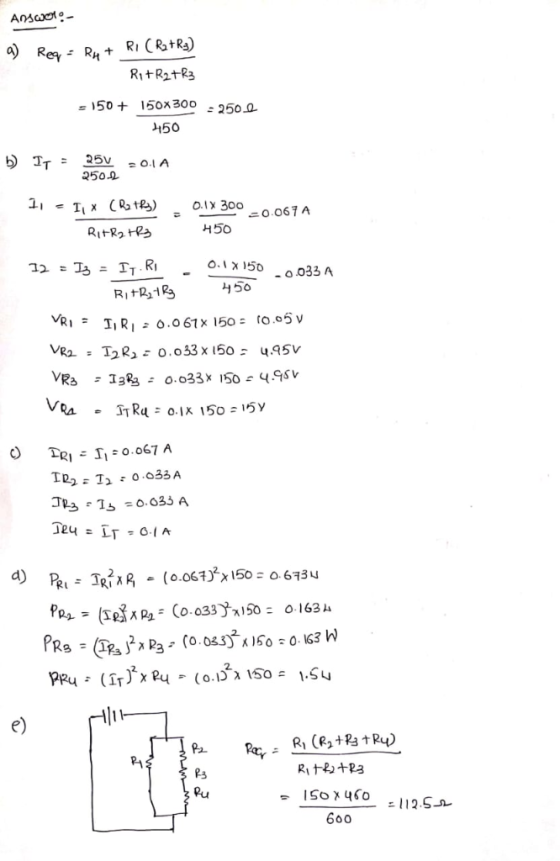
 R1 R3 Question 4 (20 points) Choose values of resistors and the voltage of the source. a) Determine the voltage drop across each resistor. b) Determine the current through each resistor. c) Determine the power supplied by the source and dissipated by each resistor. Show all steps and all calculations. Fill these values into the table below. d) This circuit is going to be used in high temperature applications. If the copper wires are originally at 20.0 °C and raised...
The circuit shown in the figure below contains three resistors (R4, R2, and R3) and three...
 The circuit shown in the figure below contains three resistors (R4, R2, and R3) and three batteries (VA, Vg, and V). The resistor values are:R1-2 Ohms, R=R3=6 Ohms, and the battery voltages are Va=25V, Vg=15 V, and Vc-20 V. When the circuit is connected, what will be the power dissipated by R2? Vc R1 + Ve R2 R3 O 1.0W O 20W O 5.0W O 60W O 7.5 W
Consider the electric circuit shown in the figure. Assume that the voltage of the battery is...
 Consider the electric circuit shown in the figure. Assume that
the voltage of the battery is V = 23.5 V, and the resistors are
R1 = R2 = R3 = R4 =
R5 = 2.00 Ω.
What is the equivalent resistance of the circuit?
What is the electric current flowing through resistor
R3?
Consider the electri = R4 = R5 = 2.00 2 circuit shown in the figure. Assume that the voltage of the battery is V = 23.5 V,...
Consider the electric circuit shown in the figure. Assume that
the voltage of the battery is V = 23.5 V, and the resistors are
R1 = R2 = R3 = R4 =
R5 = 2.00 Ω.
What is the equivalent resistance of the circuit?
What is the electric current flowing through resistor
R3?
Consider the electri = R4 = R5 = 2.00 2 circuit shown in the figure. Assume that the voltage of the battery is V = 23.5 V,...
The circuit shown in the figure below contains three resistors (R4, R2, and R3) and three...
 The circuit shown in the figure below contains three resistors (R4, R2, and R3) and three batteries (VA, VB, and V). The resistor values are: R2-2 Ohms, R2=R3=8 Ohms, and the battery voltages are VA-25V, Vp-15V, and Vc-20 V. When the circuit is connected, what will be the power dissipated by R3? VC +H R1 VA th ++ VB R2 [m R3 O 0.75 W 1.25 W O 2.67 4.2 W 5.5 W
The circuit shown in the figure below contains three resistors (R1, R2, and R3) and three...
 The circuit shown in the figure below contains three resistors (R1, R2, and R3) and three batteries (VA, VB, and Vc). The resistor values are: R1=2 Ohms, R2=R3=4 Ohms, and the battery voltages are VA=25V, V8=15 V, and Vc=20 V. When the circuit is connected, what will be the power dissipated by Ri? VC + HA R1 VA V - R2 R3 O 1.25 W 0 2.0 W O 12.5 W O 6.25 W O 8.13 W
A circuit is constructed with five resistors and one real battery as shown above right. We...
 A circuit is constructed with
five resistors and one real battery as shown above right. We model.
The real battery as an ideal emf V = 12 V in series with an
internal resistance r as shown above left. The values for the
resistors are: R1 = R3 = 22 Ω, R4 = R5 = 82 Ω and R2 = 147 Ω. The
measured voltage across the terminals of the batery is Vbattery =
11.6 V.
A circuit is constructed...
A circuit is constructed with
five resistors and one real battery as shown above right. We model.
The real battery as an ideal emf V = 12 V in series with an
internal resistance r as shown above left. The values for the
resistors are: R1 = R3 = 22 Ω, R4 = R5 = 82 Ω and R2 = 147 Ω. The
measured voltage across the terminals of the batery is Vbattery =
11.6 V.
A circuit is constructed...
A circuit is constructed with five resistors and a battery as shown. The values for the...
 A circuit is constructed with five resistors and a battery as shown. The values for the resistors are: R1 = R5 = 43 A, R2 = 121 , R3 = 64, and R4 = 1300. The battery voltage is V = 12 V. R1 b 4 Ra R5 1) What is Rab, the equivalent resistance between points a and b? 76.92 Submit 2) What is Rac, the equivalent resistance between points a and c? 119.9 Submit 3) What is 15,...
A four-resistor circuit is shown in the figure. The values of the resistors are as follows:...
 A four-resistor circuit is shown in the figure. The values of the resistors are as follows: Ri=10 Ohms, Rz=R3=6 Ohms, R4=2 Ohms. What is the equivalent resistance Reg for this circuit? R M R3 R3 R3 > O 0.50 ohms O 2.00 ohms 0 3.33 ohms 0 5.25 ohms o 7.50 ohms Question 8 5 pts The circuit shown in the figure below contains three resistors (R1, R2, and R3) and three batteries (VA. VB, and Vc). The resistor values...
A four-resistor circuit is shown in the figure. The values of the resistors are as follows:...
 A four-resistor circuit is shown in the figure. The values of
the resistors are as follows: R1=4 Ohms,
R2=R3=R4=3 Ohms. What is the
equivalent resistance Req for this circuit?
R4 R1 R23 R₂ }
A four-resistor circuit is shown in the figure. The values of
the resistors are as follows: R1=4 Ohms,
R2=R3=R4=3 Ohms. What is the
equivalent resistance Req for this circuit?
R4 R1 R23 R₂ }
You have an ideal 17 V battery (no internal resistance) connected to the circuit shown above....
 You have an ideal 17 V battery (no internal resistance) connected to the circuit shown above. R1 = 25 12, R2 = 6112, R3 = 37 12, and R4 = 45 12. What is the power dissipated in the resistor, R4? Give your answer in watts, to three significant figures. E
 R1 R3 Question 4 (20 points) Choose values of resistors and the voltage of the source. a) Determine the voltage drop across each resistor. b) Determine the current through each resistor. c) Determine the power supplied by the source and dissipated by each resistor. Show all steps and all calculations. Fill these values into the table below. d) This circuit is going to be used in high temperature applications. If the copper wires are originally at 20.0 °C and raised...
 The circuit shown in the figure below contains three resistors (R4, R2, and R3) and three batteries (VA, Vg, and V). The resistor values are:R1-2 Ohms, R=R3=6 Ohms, and the battery voltages are Va=25V, Vg=15 V, and Vc-20 V. When the circuit is connected, what will be the power dissipated by R2? Vc R1 + Ve R2 R3 O 1.0W O 20W O 5.0W O 60W O 7.5 W
 Consider the electric circuit shown in the figure. Assume that
the voltage of the battery is V = 23.5 V, and the resistors are
R1 = R2 = R3 = R4 =
R5 = 2.00 Ω.
What is the equivalent resistance of the circuit?
What is the electric current flowing through resistor
R3?
Consider the electri = R4 = R5 = 2.00 2 circuit shown in the figure. Assume that the voltage of the battery is V = 23.5 V,...
Consider the electric circuit shown in the figure. Assume that
the voltage of the battery is V = 23.5 V, and the resistors are
R1 = R2 = R3 = R4 =
R5 = 2.00 Ω.
What is the equivalent resistance of the circuit?
What is the electric current flowing through resistor
R3?
Consider the electri = R4 = R5 = 2.00 2 circuit shown in the figure. Assume that the voltage of the battery is V = 23.5 V,...
 The circuit shown in the figure below contains three resistors (R4, R2, and R3) and three batteries (VA, VB, and V). The resistor values are: R2-2 Ohms, R2=R3=8 Ohms, and the battery voltages are VA-25V, Vp-15V, and Vc-20 V. When the circuit is connected, what will be the power dissipated by R3? VC +H R1 VA th ++ VB R2 [m R3 O 0.75 W 1.25 W O 2.67 4.2 W 5.5 W
 The circuit shown in the figure below contains three resistors (R1, R2, and R3) and three batteries (VA, VB, and Vc). The resistor values are: R1=2 Ohms, R2=R3=4 Ohms, and the battery voltages are VA=25V, V8=15 V, and Vc=20 V. When the circuit is connected, what will be the power dissipated by Ri? VC + HA R1 VA V - R2 R3 O 1.25 W 0 2.0 W O 12.5 W O 6.25 W O 8.13 W
 A circuit is constructed with
five resistors and one real battery as shown above right. We model.
The real battery as an ideal emf V = 12 V in series with an
internal resistance r as shown above left. The values for the
resistors are: R1 = R3 = 22 Ω, R4 = R5 = 82 Ω and R2 = 147 Ω. The
measured voltage across the terminals of the batery is Vbattery =
11.6 V.
A circuit is constructed...
A circuit is constructed with
five resistors and one real battery as shown above right. We model.
The real battery as an ideal emf V = 12 V in series with an
internal resistance r as shown above left. The values for the
resistors are: R1 = R3 = 22 Ω, R4 = R5 = 82 Ω and R2 = 147 Ω. The
measured voltage across the terminals of the batery is Vbattery =
11.6 V.
A circuit is constructed...
 A circuit is constructed with five resistors and a battery as shown. The values for the resistors are: R1 = R5 = 43 A, R2 = 121 , R3 = 64, and R4 = 1300. The battery voltage is V = 12 V. R1 b 4 Ra R5 1) What is Rab, the equivalent resistance between points a and b? 76.92 Submit 2) What is Rac, the equivalent resistance between points a and c? 119.9 Submit 3) What is 15,...
 A four-resistor circuit is shown in the figure. The values of the resistors are as follows: Ri=10 Ohms, Rz=R3=6 Ohms, R4=2 Ohms. What is the equivalent resistance Reg for this circuit? R M R3 R3 R3 > O 0.50 ohms O 2.00 ohms 0 3.33 ohms 0 5.25 ohms o 7.50 ohms Question 8 5 pts The circuit shown in the figure below contains three resistors (R1, R2, and R3) and three batteries (VA. VB, and Vc). The resistor values...
 A four-resistor circuit is shown in the figure. The values of
the resistors are as follows: R1=4 Ohms,
R2=R3=R4=3 Ohms. What is the
equivalent resistance Req for this circuit?
R4 R1 R23 R₂ }
A four-resistor circuit is shown in the figure. The values of
the resistors are as follows: R1=4 Ohms,
R2=R3=R4=3 Ohms. What is the
equivalent resistance Req for this circuit?
R4 R1 R23 R₂ }
 You have an ideal 17 V battery (no internal resistance) connected to the circuit shown above. R1 = 25 12, R2 = 6112, R3 = 37 12, and R4 = 45 12. What is the power dissipated in the resistor, R4? Give your answer in watts, to three significant figures. E
Most questions answered within 3 hours.
-
The activation energy for a given reaction is 50.3 kJ/mol. If
the rate constant for the...
asked 25 minutes ago -
An entomologist discovers a dung beetle rolling a ball of dung
along the ground, and decides...
asked 2 hours ago -
Humans have used horses for transportation for millions of
years. Therefore, they will use horses for...
asked 4 hours ago -
The following are the Jensen Corporation's unit costs of making
and selling an item at a...
asked 4 hours ago -
Does direct Medicare reimbursement of Advanced practice nurses
increase access to their services?
asked 5 hours ago -
List and explain why a company would choose to use a
published
compensation survey vs. creating...
asked 5 hours ago -
A discrete random variable X can take values from 1 to 10. Find
the variance of...
asked 5 hours ago -
The primary financial goal of a corporation is to maximize:
shareholders wealth.
earnings per share.
stock...
asked 5 hours ago -
determine whether the vectors u=(1,2,3,), v=(-2,1,0) and
w=(1,0,1) are linearly dependent or independent.
asked 6 hours ago -
python
Define a function called print_values which takes a dictionary
object as a parameter. The function...
asked 7 hours ago -
In Chapter 1 you created a program named Triangle in
which you displayed a seven-line triangle...
asked 6 hours ago -
Research question: What are the differences between separately
stated and non separately stated transactions in an...
asked 7 hours ago