
Homework Answers


Add Answer to:
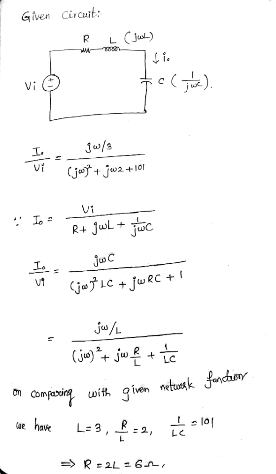
6.) Design the series resonant circuit shown in Figure 5 to have the network function ()...
For the following resonant series circuit shown in fig. 1, find : - Quality factor, Q....
 For the following resonant series circuit shown in fig. 1, find : - Quality factor, Q. - Bandwidth, B. - The voltage across the capacitor. - The voltage across the inductor. - The voltage across the resistor. L = 4.7 mH C = 0.001uF S R = 470 VIN-1 V Fig. 1 Resonant series circuit
12.18 Find the transfer function G(0) using the Bode magnitude plot shown below. Hw G/dB) -20...
 12.18 Find the transfer function G(0) using the Bode magnitude plot shown below. Hw G/dB) -20 dB/decade 40 20 100 20 (rad/s) Figure P12.18 12.26 For the following circuit determine the resonant frequency and quality factor. c = 10 nF 2mA R,2k L0.1 mH c
Question 5 For the system shown in Figure 4a whose frequency response curves for G, and...
 Question 5 For the system shown in Figure 4a whose frequency response curves for G, and G2 have been experimentally determined in Figure 4b, (a) Construct the asymptotic Bode magnitude plot of open-loop transfer function G= G1G2; (b) Determine the open-loop transfer function G-GG2; (e) Find the gain cross-over frequency from the asymptotic Bode magnitude plot of the open-loop transfer function. COD) R(D) +( EHGDAG(D) 62 0.01 0 1 10 100 (6) Figure 4
Consider the following transfer function of a bandpass filter: 20 1,500 T(S) = 2 1,500 +...
 Consider the following transfer function of a bandpass filter: 20 1,500 T(S) = 2 1,500 + 1)(30.000 +1) a) Draw the Bode plot (magnitude and phase) of T(s). Label the slopes (dB/decade) b) Name the filter type. c) Determine the resonant frequency o d) Determine the gain in dB at the resonant frequency e) Determine bandwidth B, and the quality factor of the filter. Magnitude (dB) Phase (Deg)
(a) For the circuit of Figure 4, assuming a sinusoidal is(t) (0) Prove that the resonant frequeney is given by o- (3 marks) LC (ii) If the total admittance at resonance is 20 ms (seen by the source)...
 (a) For the circuit of Figure 4, assuming a sinusoidal is(t) (0) Prove that the resonant frequeney is given by o- (3 marks) LC (ii) If the total admittance at resonance is 20 ms (seen by the source) with resonant frequency of wo 5000 rad/s and quality factor of Q-10, calculate the values of R L, C, the bandwidth and half-power frequencies in Hertz. (4 marks) VG and hence show (iii) Derive an expression for the driving point impedance Z(jø)...
Please answer all parts Problem #5 - (20%) A circuit has the transfer function: H(S) =...
 Please answer all parts
Problem #5 - (20%) A circuit has the transfer function: H(S) = S. (s + 5623 (s + 31.62) · (s + 17778) (a) Use asymptotic analysys to compute (HS) at infinite frequency by inspection of the circuit (not by computation). Express your answer in dB. (4%) (b) Determine the phase of the transfer function at infinite frequency. (4%) (c) Rewrite the transfer function in the form used for creating a Bode plot. (4%) Problem #5...
Please answer all parts
Problem #5 - (20%) A circuit has the transfer function: H(S) = S. (s + 5623 (s + 31.62) · (s + 17778) (a) Use asymptotic analysys to compute (HS) at infinite frequency by inspection of the circuit (not by computation). Express your answer in dB. (4%) (b) Determine the phase of the transfer function at infinite frequency. (4%) (c) Rewrite the transfer function in the form used for creating a Bode plot. (4%) Problem #5...
Prob. 5 (30 pts): You are to design a compensator for a radar antenna as shown...
 Prob. 5 (30 pts): You are to design a compensator for a radar antenna as shown below. Determine G. (s) so that (a)* The closed-loop system has a bandwidth of approximately 20 rad/s. (b) The closed loop system must have positive phase margin. (6) Increase the attenuation at 200 rad/sec or higher. *You can assume that the bandwidth of the closed system is equal to the gain crossover frequency of the open loop system. You may wish to use the...
C 1m2 w 1E-4 1E-10 2.1: What is the resonant frequency of the circuit? 2.2: When...
 C 1m2 w 1E-4 1E-10 2.1: What is the resonant frequency of the circuit? 2.2: When R = 100.01 kO 1. What is the damping ratio, 5? 2. Sketch the Bode plot of the magnitude (dB-log) when Vout is the voltage across the inductor, H(s) VL(s)N1(s) 3. Sketch the Bode plot of the magnitude (dB-log) when Vout is the voltage across the resistor H(s) = VR(s)N1(s) 2.3. When R = 20000, 1. What is the damping ratio, ? 2. Sketch...
8. For the RLC circuit shown, Find the half power frequencies, the resonant frequency, the bandwidth,...
 8. For the RLC circuit shown, Find the half power frequencies, the resonant frequency, the bandwidth, and the quality factor in terms of R, L and C. it) R Vin(o) (+
2. LRC series circuit. [10 pts.] Consider an LRC series circuit driven by an ac voltage source Vi...
 2. LRC series circuit. [10 pts.] Consider an LRC series circuit driven by an ac voltage source Vin Vo cos(wt). (a) Derive an expression for the real ac current in the circuit in terms of L, R, C, and a. (b) Determine the resonant frequency f, and angular frequency w, by direct differentiation of the current amplitude from part (a). Compare your result to LC (c) Determine the Q factor of this circuit in terms of L, R, and C....
 For the following resonant series circuit shown in fig. 1, find : - Quality factor, Q. - Bandwidth, B. - The voltage across the capacitor. - The voltage across the inductor. - The voltage across the resistor. L = 4.7 mH C = 0.001uF S R = 470 VIN-1 V Fig. 1 Resonant series circuit
 12.18 Find the transfer function G(0) using the Bode magnitude plot shown below. Hw G/dB) -20 dB/decade 40 20 100 20 (rad/s) Figure P12.18 12.26 For the following circuit determine the resonant frequency and quality factor. c = 10 nF 2mA R,2k L0.1 mH c
 Question 5 For the system shown in Figure 4a whose frequency response curves for G, and G2 have been experimentally determined in Figure 4b, (a) Construct the asymptotic Bode magnitude plot of open-loop transfer function G= G1G2; (b) Determine the open-loop transfer function G-GG2; (e) Find the gain cross-over frequency from the asymptotic Bode magnitude plot of the open-loop transfer function. COD) R(D) +( EHGDAG(D) 62 0.01 0 1 10 100 (6) Figure 4
 Consider the following transfer function of a bandpass filter: 20 1,500 T(S) = 2 1,500 + 1)(30.000 +1) a) Draw the Bode plot (magnitude and phase) of T(s). Label the slopes (dB/decade) b) Name the filter type. c) Determine the resonant frequency o d) Determine the gain in dB at the resonant frequency e) Determine bandwidth B, and the quality factor of the filter. Magnitude (dB) Phase (Deg)
 (a) For the circuit of Figure 4, assuming a sinusoidal is(t) (0) Prove that the resonant frequeney is given by o- (3 marks) LC (ii) If the total admittance at resonance is 20 ms (seen by the source) with resonant frequency of wo 5000 rad/s and quality factor of Q-10, calculate the values of R L, C, the bandwidth and half-power frequencies in Hertz. (4 marks) VG and hence show (iii) Derive an expression for the driving point impedance Z(jø)...
 Please answer all parts
Problem #5 - (20%) A circuit has the transfer function: H(S) = S. (s + 5623 (s + 31.62) · (s + 17778) (a) Use asymptotic analysys to compute (HS) at infinite frequency by inspection of the circuit (not by computation). Express your answer in dB. (4%) (b) Determine the phase of the transfer function at infinite frequency. (4%) (c) Rewrite the transfer function in the form used for creating a Bode plot. (4%) Problem #5...
Please answer all parts
Problem #5 - (20%) A circuit has the transfer function: H(S) = S. (s + 5623 (s + 31.62) · (s + 17778) (a) Use asymptotic analysys to compute (HS) at infinite frequency by inspection of the circuit (not by computation). Express your answer in dB. (4%) (b) Determine the phase of the transfer function at infinite frequency. (4%) (c) Rewrite the transfer function in the form used for creating a Bode plot. (4%) Problem #5...
 Prob. 5 (30 pts): You are to design a compensator for a radar antenna as shown below. Determine G. (s) so that (a)* The closed-loop system has a bandwidth of approximately 20 rad/s. (b) The closed loop system must have positive phase margin. (6) Increase the attenuation at 200 rad/sec or higher. *You can assume that the bandwidth of the closed system is equal to the gain crossover frequency of the open loop system. You may wish to use the...
 C 1m2 w 1E-4 1E-10 2.1: What is the resonant frequency of the circuit? 2.2: When R = 100.01 kO 1. What is the damping ratio, 5? 2. Sketch the Bode plot of the magnitude (dB-log) when Vout is the voltage across the inductor, H(s) VL(s)N1(s) 3. Sketch the Bode plot of the magnitude (dB-log) when Vout is the voltage across the resistor H(s) = VR(s)N1(s) 2.3. When R = 20000, 1. What is the damping ratio, ? 2. Sketch...
 8. For the RLC circuit shown, Find the half power frequencies, the resonant frequency, the bandwidth, and the quality factor in terms of R, L and C. it) R Vin(o) (+
 2. LRC series circuit. [10 pts.] Consider an LRC series circuit driven by an ac voltage source Vin Vo cos(wt). (a) Derive an expression for the real ac current in the circuit in terms of L, R, C, and a. (b) Determine the resonant frequency f, and angular frequency w, by direct differentiation of the current amplitude from part (a). Compare your result to LC (c) Determine the Q factor of this circuit in terms of L, R, and C....
Most questions answered within 3 hours.
-
Function 4: my-map
In CLISP define your own function that duplicates the
functionality of mapcar from...
asked 24 minutes ago -
Imagine you are progressing very well
during your job interview and you are confidently prepared to...
asked 23 minutes ago -
You have 2.50 L of a 0.450 M HCOOH and 0.550 M HCOONa buffer
solution. (Ka...
asked 25 minutes ago -
The Maxit Corporation has a standard costing system in which
variable manufacturing overhead is assigned to...
asked 43 minutes ago -
Let M = 8.00kg, m = 6.00kg, θ = 40.00, and the coefficient of
kinetic friction...
asked 1 hour ago -
Java. For C through H True or false?
c. Primitive variables must be objects.
d. Integer...
asked 1 hour ago -
Write a program that turns a 32-bit numeric value (e.g.,
0xFFFFh) and converts it to a...
asked 1 hour ago -
A motor produces a torque of 0.25 N m at an angular velocity of
7200 revolutions...
asked 1 hour ago -
***Please answer the below java question***
Are static methods inheritable? Can they be overridden?
asked 1 hour ago -
In reaching her destination, a backpacker walks with an average
velocity of 1.13 m/s, due west....
asked 1 hour ago -
Write two C programs that run a
server program and a client program concurrently.
Server program:...
asked 1 hour ago -
Executive Program Practical Connection Assignment
Subject : Operations Security.
Assignment:
Provide a reflection of at least...
asked 1 hour ago