

cN you please help me with question 2
Homework Answers


Add Answer to:
cN you please help me with question 2
t Figure 2.3, reasure RnLİ" İhandl, using the...
ercise 2 Part One: Verify the operation modes of various transistor configurations fask 2.1.1: atermine the...
 ercise 2 Part One: Verify the operation modes of various transistor configurations fask 2.1.1: atermine the input resistance, output resistance, small-signal voltage gain and low-frequency cut-off of the circuits in Figure 2.2, given that gm 3mS for the circuit on the left and 24mS for the circuit on the right. You may assume that CS has been chosen so that its impedance is 'small' at the frequencies of interest. Use simulation to verify your solution. V DD 15 V Voo-12...
In Figure 9, the transformer primary voltage is 120V and step-downratiois 10:1 Assume the practical diode...
 In Figure 9, the transformer primary voltage is 120V and step-downratiois 10:1 Assume the practical diode model. 9. a) i) Name the type of circuit (1 mark) Determine the peak output voltage, Volout) (4 marks) iiI What is the PIV rating required for the diodes (2 marks) D, D3 120 V psecy R Plout) 10 k2 DA Figure 9 b) A certain power supply filter produces an output with a ripple of 100mV peak-to- peak and a dc value of...
IV, Laboratory Procedure 1. Construct the circuit of Figure 6.1, measure the current value 2. Con...
 IV, Laboratory Procedure 1. Construct the circuit of Figure 6.1, measure the current value 2. Construct the circuit of Figure 6.2; measure Vn and v., using the oscilloscope. 3. Construct the circuit of Figure 6.3, measure the value of Io and V 4. Construct the clipper design circuit, Capture the input and output waveforms. 5. Construct your clamper design circuit. Capture the input and output waveforms Figure 6.3 Design a clipper circuit which limits input signals to +3V and -2V....
using the circuit above as refernce solve problem 3 . Construct Figure 2.3, using VCC-5 V, RI -6.8k2, R2 3.3k, C10.luF, and C2 -0.0luF. R1 6.sk R2 3.3k THRES OUT SV x1 C2 0.01u o.1u Figure 2.3 2....
 using the circuit above as refernce solve problem 3
. Construct Figure 2.3, using VCC-5 V, RI -6.8k2, R2 3.3k, C10.luF, and C2 -0.0luF. R1 6.sk R2 3.3k THRES OUT SV x1 C2 0.01u o.1u Figure 2.3 2. Enter your results below. Duty Cycle Turn ON Time ToN Total Time Period | Turn OFF Time Quantity Measured Theoretical Value Design a circuit for a duty cycle 75%, and a frequency of 1 KHz. Show all calculations and results. 3. 4....
using the circuit above as refernce solve problem 3
. Construct Figure 2.3, using VCC-5 V, RI -6.8k2, R2 3.3k, C10.luF, and C2 -0.0luF. R1 6.sk R2 3.3k THRES OUT SV x1 C2 0.01u o.1u Figure 2.3 2. Enter your results below. Duty Cycle Turn ON Time ToN Total Time Period | Turn OFF Time Quantity Measured Theoretical Value Design a circuit for a duty cycle 75%, and a frequency of 1 KHz. Show all calculations and results. 3. 4....
using the circuit above as refernce solve problem 3 . Construct Figure 2.3, using VCC-5 V,...
 using the circuit above as refernce solve problem 3
. Construct Figure 2.3, using VCC-5 V, RI -6.8k2, R2 3.3k, C10.luF, and C2 -0.0luF. R1 6.sk R2 3.3k THRES OUT SV x1 C2 0.01u o.1u Figure 2.3 2. Enter your results below. Duty Cycle Turn ON Time ToN Total Time Period | Turn OFF Time Quantity Measured Theoretical Value Design a circuit for a duty cycle 75%, and a frequency of 1 KHz. Show all calculations and results. 3. 4.
using the circuit above as refernce solve problem 3
. Construct Figure 2.3, using VCC-5 V, RI -6.8k2, R2 3.3k, C10.luF, and C2 -0.0luF. R1 6.sk R2 3.3k THRES OUT SV x1 C2 0.01u o.1u Figure 2.3 2. Enter your results below. Duty Cycle Turn ON Time ToN Total Time Period | Turn OFF Time Quantity Measured Theoretical Value Design a circuit for a duty cycle 75%, and a frequency of 1 KHz. Show all calculations and results. 3. 4.
Please answer me step by step thanks Question 2: Th is question relates to diodes and...
 Please answer me step by step thanks
Question 2: Th is question relates to diodes and transistor amplifiers The following question relates to the diode circuit in Figure 2a below. if t E- SV, and the diode was a Red LED, determine; (i) the voltage across the diode, Vo (ii) the value of resistor R, that will give a current, 1 4mA (ii) the current, I, if E--5V (a) he voltage source Figure 2a 8 marks] er amplifier circuit shown...
Please answer me step by step thanks
Question 2: Th is question relates to diodes and transistor amplifiers The following question relates to the diode circuit in Figure 2a below. if t E- SV, and the diode was a Red LED, determine; (i) the voltage across the diode, Vo (ii) the value of resistor R, that will give a current, 1 4mA (ii) the current, I, if E--5V (a) he voltage source Figure 2a 8 marks] er amplifier circuit shown...
can someone help me with part c mpt tope alswersol the sdme part of you willbe penalized for this. Question 1 1 pts For the circuit shown in Figure 6.49, let Vcc -9V.RE 0.11 kQ, R1 3.6 k2, R2 5.6...
 can someone help me with part c
mpt tope alswersol the sdme part of you willbe penalized for this. Question 1 1 pts For the circuit shown in Figure 6.49, let Vcc -9V.RE 0.11 kQ, R1 3.6 k2, R2 5.6k(2, and Rs -o Ω . The transistor parameters are β-200. VBE(On)-Q7V, VA - 100 V and VT 0.026 V.(a) Determine the quiescent value of lEQ. (b) Find the small-signal voltage gain Av-vo/vg (c) Determine the output resistance Ro looking into...
can someone help me with part c
mpt tope alswersol the sdme part of you willbe penalized for this. Question 1 1 pts For the circuit shown in Figure 6.49, let Vcc -9V.RE 0.11 kQ, R1 3.6 k2, R2 5.6k(2, and Rs -o Ω . The transistor parameters are β-200. VBE(On)-Q7V, VA - 100 V and VT 0.026 V.(a) Determine the quiescent value of lEQ. (b) Find the small-signal voltage gain Av-vo/vg (c) Determine the output resistance Ro looking into...
ANSWER ALL PLEASE Question 20 2 pts In the Figure below, V1 = 14 V, V2...
 ANSWER ALL PLEASE
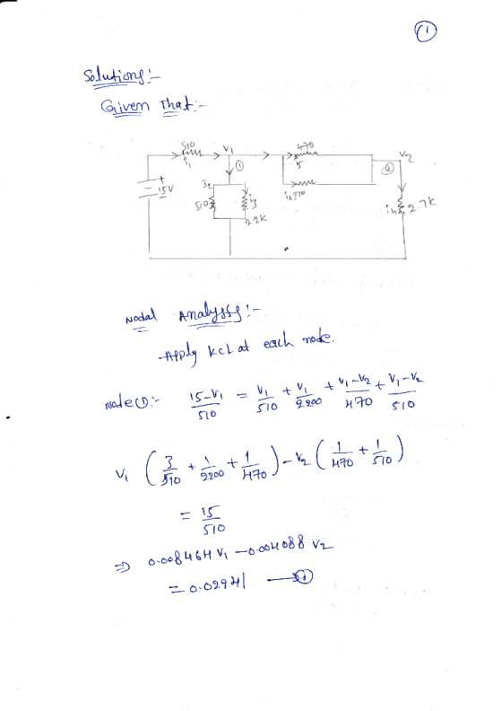
Question 20 2 pts In the Figure below, V1 = 14 V, V2 = 8 V, V3 = 10 V, R1 = 2.00, R2 = 4.0, and R3 = 2.00 Find the electric currents is, iz, and is. (Hint: use the junction a and the two loops). RI R 14 M4 Equations: Kirchoff's Junction (node) rule: 11 = 12 + iz Kirchoff's Loop rule (left loop): V1 - iRi - iz R2 + V2 = 0 Kirchoffs...
ANSWER ALL PLEASE
Question 20 2 pts In the Figure below, V1 = 14 V, V2 = 8 V, V3 = 10 V, R1 = 2.00, R2 = 4.0, and R3 = 2.00 Find the electric currents is, iz, and is. (Hint: use the junction a and the two loops). RI R 14 M4 Equations: Kirchoff's Junction (node) rule: 11 = 12 + iz Kirchoff's Loop rule (left loop): V1 - iRi - iz R2 + V2 = 0 Kirchoffs...
Please show clearly how to answer each part with work. Thank you Problem 2: The following...
 Please show clearly how to answer each part with work. Thank
you
Problem 2: The following op-amp circuit performs voltage level shifting. 尺 鈎 Let RL-20KQ, V+--V = 10V and let V be equal to one of the other supply voltages. 2.1 Let vs(t) be an AC signal of amplitude 2V and frequency f-2.5KHz riding on top of a DC signal of V. We want vo(t) to be an AC signal of amplitude 2.5V and frequency f 2.5KHz, riding on...
Please show clearly how to answer each part with work. Thank
you
Problem 2: The following op-amp circuit performs voltage level shifting. 尺 鈎 Let RL-20KQ, V+--V = 10V and let V be equal to one of the other supply voltages. 2.1 Let vs(t) be an AC signal of amplitude 2V and frequency f-2.5KHz riding on top of a DC signal of V. We want vo(t) to be an AC signal of amplitude 2.5V and frequency f 2.5KHz, riding on...
Exercise #4 Voltage Divider A. Introduction In a previous exercise, you learned about the current-voltage relationship...
 Exercise #4 Voltage Divider A. Introduction In a previous exercise, you learned about the current-voltage relationship in a single resistor. Now, you will about how voltage is divided across two resistors in series. In this exercise you will: Examine the operation of the electric circuit known as the voltape divicder At the conclusion of this exercise you should be able to Compute the valtage across a resistor in a voltage divider circuit Design a voltage divider circuit to produce a...
 ercise 2 Part One: Verify the operation modes of various transistor configurations fask 2.1.1: atermine the input resistance, output resistance, small-signal voltage gain and low-frequency cut-off of the circuits in Figure 2.2, given that gm 3mS for the circuit on the left and 24mS for the circuit on the right. You may assume that CS has been chosen so that its impedance is 'small' at the frequencies of interest. Use simulation to verify your solution. V DD 15 V Voo-12...
 In Figure 9, the transformer primary voltage is 120V and step-downratiois 10:1 Assume the practical diode model. 9. a) i) Name the type of circuit (1 mark) Determine the peak output voltage, Volout) (4 marks) iiI What is the PIV rating required for the diodes (2 marks) D, D3 120 V psecy R Plout) 10 k2 DA Figure 9 b) A certain power supply filter produces an output with a ripple of 100mV peak-to- peak and a dc value of...
 IV, Laboratory Procedure 1. Construct the circuit of Figure 6.1, measure the current value 2. Construct the circuit of Figure 6.2; measure Vn and v., using the oscilloscope. 3. Construct the circuit of Figure 6.3, measure the value of Io and V 4. Construct the clipper design circuit, Capture the input and output waveforms. 5. Construct your clamper design circuit. Capture the input and output waveforms Figure 6.3 Design a clipper circuit which limits input signals to +3V and -2V....
 using the circuit above as refernce solve problem 3
. Construct Figure 2.3, using VCC-5 V, RI -6.8k2, R2 3.3k, C10.luF, and C2 -0.0luF. R1 6.sk R2 3.3k THRES OUT SV x1 C2 0.01u o.1u Figure 2.3 2. Enter your results below. Duty Cycle Turn ON Time ToN Total Time Period | Turn OFF Time Quantity Measured Theoretical Value Design a circuit for a duty cycle 75%, and a frequency of 1 KHz. Show all calculations and results. 3. 4....
using the circuit above as refernce solve problem 3
. Construct Figure 2.3, using VCC-5 V, RI -6.8k2, R2 3.3k, C10.luF, and C2 -0.0luF. R1 6.sk R2 3.3k THRES OUT SV x1 C2 0.01u o.1u Figure 2.3 2. Enter your results below. Duty Cycle Turn ON Time ToN Total Time Period | Turn OFF Time Quantity Measured Theoretical Value Design a circuit for a duty cycle 75%, and a frequency of 1 KHz. Show all calculations and results. 3. 4....
 using the circuit above as refernce solve problem 3
. Construct Figure 2.3, using VCC-5 V, RI -6.8k2, R2 3.3k, C10.luF, and C2 -0.0luF. R1 6.sk R2 3.3k THRES OUT SV x1 C2 0.01u o.1u Figure 2.3 2. Enter your results below. Duty Cycle Turn ON Time ToN Total Time Period | Turn OFF Time Quantity Measured Theoretical Value Design a circuit for a duty cycle 75%, and a frequency of 1 KHz. Show all calculations and results. 3. 4.
using the circuit above as refernce solve problem 3
. Construct Figure 2.3, using VCC-5 V, RI -6.8k2, R2 3.3k, C10.luF, and C2 -0.0luF. R1 6.sk R2 3.3k THRES OUT SV x1 C2 0.01u o.1u Figure 2.3 2. Enter your results below. Duty Cycle Turn ON Time ToN Total Time Period | Turn OFF Time Quantity Measured Theoretical Value Design a circuit for a duty cycle 75%, and a frequency of 1 KHz. Show all calculations and results. 3. 4.
 Please answer me step by step thanks
Question 2: Th is question relates to diodes and transistor amplifiers The following question relates to the diode circuit in Figure 2a below. if t E- SV, and the diode was a Red LED, determine; (i) the voltage across the diode, Vo (ii) the value of resistor R, that will give a current, 1 4mA (ii) the current, I, if E--5V (a) he voltage source Figure 2a 8 marks] er amplifier circuit shown...
Please answer me step by step thanks
Question 2: Th is question relates to diodes and transistor amplifiers The following question relates to the diode circuit in Figure 2a below. if t E- SV, and the diode was a Red LED, determine; (i) the voltage across the diode, Vo (ii) the value of resistor R, that will give a current, 1 4mA (ii) the current, I, if E--5V (a) he voltage source Figure 2a 8 marks] er amplifier circuit shown...
 can someone help me with part c
mpt tope alswersol the sdme part of you willbe penalized for this. Question 1 1 pts For the circuit shown in Figure 6.49, let Vcc -9V.RE 0.11 kQ, R1 3.6 k2, R2 5.6k(2, and Rs -o Ω . The transistor parameters are β-200. VBE(On)-Q7V, VA - 100 V and VT 0.026 V.(a) Determine the quiescent value of lEQ. (b) Find the small-signal voltage gain Av-vo/vg (c) Determine the output resistance Ro looking into...
can someone help me with part c
mpt tope alswersol the sdme part of you willbe penalized for this. Question 1 1 pts For the circuit shown in Figure 6.49, let Vcc -9V.RE 0.11 kQ, R1 3.6 k2, R2 5.6k(2, and Rs -o Ω . The transistor parameters are β-200. VBE(On)-Q7V, VA - 100 V and VT 0.026 V.(a) Determine the quiescent value of lEQ. (b) Find the small-signal voltage gain Av-vo/vg (c) Determine the output resistance Ro looking into...
 ANSWER ALL PLEASE
Question 20 2 pts In the Figure below, V1 = 14 V, V2 = 8 V, V3 = 10 V, R1 = 2.00, R2 = 4.0, and R3 = 2.00 Find the electric currents is, iz, and is. (Hint: use the junction a and the two loops). RI R 14 M4 Equations: Kirchoff's Junction (node) rule: 11 = 12 + iz Kirchoff's Loop rule (left loop): V1 - iRi - iz R2 + V2 = 0 Kirchoffs...
ANSWER ALL PLEASE
Question 20 2 pts In the Figure below, V1 = 14 V, V2 = 8 V, V3 = 10 V, R1 = 2.00, R2 = 4.0, and R3 = 2.00 Find the electric currents is, iz, and is. (Hint: use the junction a and the two loops). RI R 14 M4 Equations: Kirchoff's Junction (node) rule: 11 = 12 + iz Kirchoff's Loop rule (left loop): V1 - iRi - iz R2 + V2 = 0 Kirchoffs...
 Please show clearly how to answer each part with work. Thank
you
Problem 2: The following op-amp circuit performs voltage level shifting. 尺 鈎 Let RL-20KQ, V+--V = 10V and let V be equal to one of the other supply voltages. 2.1 Let vs(t) be an AC signal of amplitude 2V and frequency f-2.5KHz riding on top of a DC signal of V. We want vo(t) to be an AC signal of amplitude 2.5V and frequency f 2.5KHz, riding on...
Please show clearly how to answer each part with work. Thank
you
Problem 2: The following op-amp circuit performs voltage level shifting. 尺 鈎 Let RL-20KQ, V+--V = 10V and let V be equal to one of the other supply voltages. 2.1 Let vs(t) be an AC signal of amplitude 2V and frequency f-2.5KHz riding on top of a DC signal of V. We want vo(t) to be an AC signal of amplitude 2.5V and frequency f 2.5KHz, riding on...
 Exercise #4 Voltage Divider A. Introduction In a previous exercise, you learned about the current-voltage relationship in a single resistor. Now, you will about how voltage is divided across two resistors in series. In this exercise you will: Examine the operation of the electric circuit known as the voltape divicder At the conclusion of this exercise you should be able to Compute the valtage across a resistor in a voltage divider circuit Design a voltage divider circuit to produce a...
Most questions answered within 3 hours.
-
. Suppose a discrete random variable has probability
distribution
P(x) = .2 if x = 0...
asked 1 hour ago -
Problem #1
The area between Z = 0 and Z = 2.50
The area between Z...
asked 8 minutes ago -
Under the influence of its drive force, a snowmobile is moving
at a constant velocity along...
asked 1 hour ago -
Why do organizations decline? What steps can top
management take to halt, decline, and restore organizational...
asked 1 hour ago -
What mechanisms Drive speciation??
(I.e. what was Dawins theory on the orgin of species, and how...
asked 3 hours ago -
The manager at a car assembly plant believes that the mean
assembly time for a car...
asked 3 hours ago -
Which of the following is true of electron capture?
A) It decreases the nuclide's mass number...
asked 5 hours ago -
Assuming an efficiency of 43.10%, calculate the actual yield of
magnesium nitrate formed from 114.9 g...
asked 5 hours ago -
The highly pathogenic bacterium Clostridium
perfringens causes gangrene, a disease that results in the
destruction of...
asked 7 hours ago -
In the context of situation analysis, which of the following is
a category for analysis in...
asked 7 hours ago -
In a study of the gas phase decomposition of sulfuryl chloride
at 600 K SO2Cl2(g)SO2(g) +...
asked 7 hours ago -
75 g of 2-propanol (C3H8O) and 25 g of pentane are mixed in a
200 mL...
asked 7 hours ago