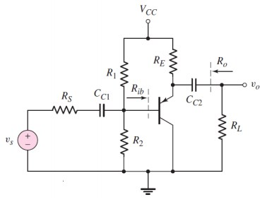
1.In the circuit below, if VCC = 5V, ?? = 4?Ω, ?1 = 60?Ω, ?2 = 40?Ω, ?? = 3?Ω, ?? = 4?Ω, ? = 75, ?? = 80?, ??? (??) = 0.7?
a. What kind of amp is the circuit? Why is that? What are its
features?
b. Find the VECQ and ICQ values. Draw the load line.
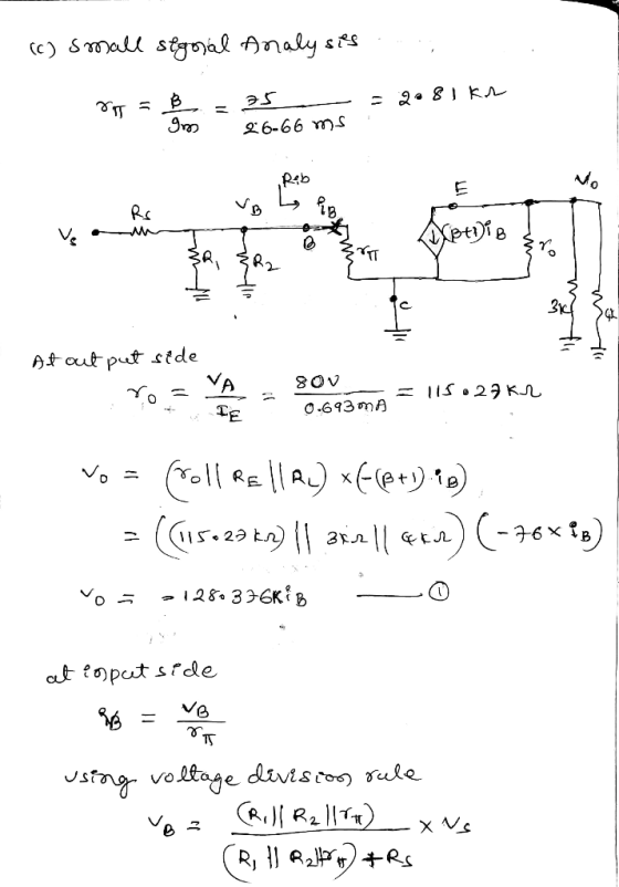
c. Draw the small signal curve circuit of the circuit. Find all the
intermediate steps of your analysis and find the voltage gain,
input and output resistors.
Homework Answers
(a) common collector amplifier used between amplifier stages for impedance matching. It has high current gain and low Voltage gain.


![Transconductance 980 = TE vp = Theron al voltage : = gomv at room temperature gos. 3 0.685mA 26mu som = 26-68 ms. ] load line](http://img.homeworklib.com/questions/2d2b3660-d5b9-11ea-a38a-696290aea1c1.png?x-oss-process=image/resize,w_560)

Problem 4 In the circuit below Vcc-VEE-5V, IE-1 mA, Rc 4kQ, and BJT has ?--50. Rc...
 Problem 4 In the circuit below Vcc-VEE-5V, IE-1 mA, Rc 4kQ, and BJT has ?--50. Rc C Le Estimate the maximum amplitude of the undistorted sine wave output voltage. -Find the voltage gain fronm signal to load for Rs = 50? and R.-4kS2. Ignore ro in your analysis and assume that coupling capacitors act as short circuits for frequencies of interest.
4. Consider the common-emitter amplifier of Figure 5. Draw the dc circuit and find ICQ. Draw the dc circuit and find IC...
 4. Consider the common-emitter amplifier of Figure 5. Draw the dc circuit and find ICQ. Draw the dc circuit and find ICQ. Find the value of Then, calculate values for Voltage gain Av, Open circuit voltage gain Avoc, input impedance Zin, current gain Ai, power gain G, and out- put impedance Zo. Assume operation in the frequency range for which influence of coupling and bypass capacitors can be ignored +15 V +15 V B 100 100 Ω 47ka Figure 5...
4. For the amplifier in the figure below use the parameters in the table: +Vcc Re VBE- 0.7V, Ri- ...
 4. For the amplifier in the figure below use the parameters in the table: +Vcc Re VBE- 0.7V, Ri- 1002, R1-160k2, R2-320k2 R3-200k2, R6-40 k2, Rc-60k2, Vcc- 12V, Ry Do a) Draw the DC equivalent circuit and calculate the Q-point. c) Draw the AC equivalent circuit with the small signal model for the transistor. d) Calculate the voltage gain, Av-Vo/vi. Assume ro infinite. e) Draw the circuit to find the amplifier input resistance (Rin). Calculate Rin f Draw the circuit...
The BJTs in the circuit below has the same β = 90 and the same collector...
 The BJTs in the circuit below has the same β = 90 and the same
collector current. Assume I = 1.9 mA, RC=900 Ω, and use VT = 25
mV.
a- What is the configuration of each stage of the amplifier?
Explain and add to the figure below the input and the output of
each stage.
b- Draw the small signal equivalent circuit and find the small
signal parameters.
c- Find the voltage gain of this amplifier
Vcc Rc Vo...
The BJTs in the circuit below has the same β = 90 and the same
collector current. Assume I = 1.9 mA, RC=900 Ω, and use VT = 25
mV.
a- What is the configuration of each stage of the amplifier?
Explain and add to the figure below the input and the output of
each stage.
b- Draw the small signal equivalent circuit and find the small
signal parameters.
c- Find the voltage gain of this amplifier
Vcc Rc Vo...
RS Given that R2-40K, R5-10K, R6-10K, R7-10K, RL 5K, C 1-1 000uF, C3-. 1 uF, C4-1 000uF, C2-0pF and Vec=1 5V. Vcc C3 n RT Vin C1 vo Draw the DC model of this circuit. a. R6 RL Find the bias volta...
 RS Given that R2-40K, R5-10K, R6-10K, R7-10K, RL 5K, C 1-1 000uF, C3-. 1 uF, C4-1 000uF, C2-0pF and Vec=1 5V. Vcc C3 n RT Vin C1 vo Draw the DC model of this circuit. a. R6 RL Find the bias voltage at pin 3 of the op amp. b. ua741 R2 C4 Find the low-frequency cut-off of this circuit. c. acts like a short circuit? What is the input current at pin 2 of the op amp? e. f....
- 1. For the MOSFET amplifier, given Vpp = 5V, -VSS=-5V, Rsig = 1Kohm, =K',(W/L)= 0.8...
 - 1. For the MOSFET amplifier, given Vpp = 5V, -VSS=-5V, Rsig = 1Kohm, =K',(W/L)= 0.8 mA/V2, Ven= 1.1V, 1 = 0, Q point (0.5mA, 5V). a. Draw small signal equivalent circuit b. To get the Q point, determine values of Rp. and RG c. Find input impedance Rin = _ and output impedance Rout=__ d. Determine the g11 = and g22 for the amplifier e. Find the voltage gain Av=vo/Vsig=_ --
The 1 mA. V, ls -VE -15 15 V, in the following differential amplifier circuit, Vcc parameters are given as β, 100, VBE# 0.7 V, pr-25 mV, K.-100 V. transistor Rc-10 kΩ For: RE-150 Ω Rc Rc REE-200...
 The 1 mA. V, ls -VE -15 15 V, in the following differential amplifier circuit, Vcc parameters are given as β, 100, VBE# 0.7 V, pr-25 mV, K.-100 V. transistor Rc-10 kΩ For: RE-150 Ω Rc Rc REE-200 kΩ a) What is the input differential resistance, Rid b) What is the overall voltage gain vV? You c) What is input common mode resistance, d) What is the worst case common mode gain that appear across the two input terminals? (4...
1. Problem 1: For the circuit below, where β-100 and VT 25mV a. Find the dc...
 1. Problem 1: For the circuit below, where β-100 and VT 25mV a. Find the dc collector current, Ic. b. Find the small signal parameters: gm , Γπ and re- c. Draw the small-signal equivalent circuit by replacing the BJT with its hybrid-t model. d. Draw the small-signal equivalent circuit by replacing the BJT with its T model. e. Use the circuit in c or d to determine the voltage gains (Ao, A.) and overall gain (Gv) 5V 1V Vout...
Need some help for this Problem 1: Consider the circuit below. Vcc = 12V, R31 =...
 Need some help for this
Problem 1: Consider the circuit below. Vcc = 12V, R31 = 120k12, RB2 = 40 k12, R33 = 120 k12, R34 = 20k12, Rei 3k12, Re2 = 1k12, Rc2= 10 kN, Rcz = 0 and B = 50. a. Calculate the collector current and emitter voltage for both transistors. Neglect Early effect b. Draw the small signal equivalent circuit. c. Calculate Rin2, Rin, Rout d. Calculate the overall gain with load of the amplifier if...
Need some help for this
Problem 1: Consider the circuit below. Vcc = 12V, R31 = 120k12, RB2 = 40 k12, R33 = 120 k12, R34 = 20k12, Rei 3k12, Re2 = 1k12, Rc2= 10 kN, Rcz = 0 and B = 50. a. Calculate the collector current and emitter voltage for both transistors. Neglect Early effect b. Draw the small signal equivalent circuit. c. Calculate Rin2, Rin, Rout d. Calculate the overall gain with load of the amplifier if...
A signal source with an open-circuit voltage of Vs = 2 mV rms and an internal...
A signal source with an open-circuit voltage of Vs = 2 mV rms and an internal resistance of 50 kΩ is connected to the input terminals of an amplifier having an open-circuit voltage gain of 100, an input resistance of 135 kΩ , and an output resistance of 4 Ω. A 4 Ω load is connected to the output terminals. Find Voltage gain Avs = V0/Vs Find voltage gain Av = V0/Vi Find current gain Ai Find power gain G...
 Problem 4 In the circuit below Vcc-VEE-5V, IE-1 mA, Rc 4kQ, and BJT has ?--50. Rc C Le Estimate the maximum amplitude of the undistorted sine wave output voltage. -Find the voltage gain fronm signal to load for Rs = 50? and R.-4kS2. Ignore ro in your analysis and assume that coupling capacitors act as short circuits for frequencies of interest.
 4. Consider the common-emitter amplifier of Figure 5. Draw the dc circuit and find ICQ. Draw the dc circuit and find ICQ. Find the value of Then, calculate values for Voltage gain Av, Open circuit voltage gain Avoc, input impedance Zin, current gain Ai, power gain G, and out- put impedance Zo. Assume operation in the frequency range for which influence of coupling and bypass capacitors can be ignored +15 V +15 V B 100 100 Ω 47ka Figure 5...
 4. For the amplifier in the figure below use the parameters in the table: +Vcc Re VBE- 0.7V, Ri- 1002, R1-160k2, R2-320k2 R3-200k2, R6-40 k2, Rc-60k2, Vcc- 12V, Ry Do a) Draw the DC equivalent circuit and calculate the Q-point. c) Draw the AC equivalent circuit with the small signal model for the transistor. d) Calculate the voltage gain, Av-Vo/vi. Assume ro infinite. e) Draw the circuit to find the amplifier input resistance (Rin). Calculate Rin f Draw the circuit...
 The BJTs in the circuit below has the same β = 90 and the same
collector current. Assume I = 1.9 mA, RC=900 Ω, and use VT = 25
mV.
a- What is the configuration of each stage of the amplifier?
Explain and add to the figure below the input and the output of
each stage.
b- Draw the small signal equivalent circuit and find the small
signal parameters.
c- Find the voltage gain of this amplifier
Vcc Rc Vo...
The BJTs in the circuit below has the same β = 90 and the same
collector current. Assume I = 1.9 mA, RC=900 Ω, and use VT = 25
mV.
a- What is the configuration of each stage of the amplifier?
Explain and add to the figure below the input and the output of
each stage.
b- Draw the small signal equivalent circuit and find the small
signal parameters.
c- Find the voltage gain of this amplifier
Vcc Rc Vo...
 RS Given that R2-40K, R5-10K, R6-10K, R7-10K, RL 5K, C 1-1 000uF, C3-. 1 uF, C4-1 000uF, C2-0pF and Vec=1 5V. Vcc C3 n RT Vin C1 vo Draw the DC model of this circuit. a. R6 RL Find the bias voltage at pin 3 of the op amp. b. ua741 R2 C4 Find the low-frequency cut-off of this circuit. c. acts like a short circuit? What is the input current at pin 2 of the op amp? e. f....
 - 1. For the MOSFET amplifier, given Vpp = 5V, -VSS=-5V, Rsig = 1Kohm, =K',(W/L)= 0.8 mA/V2, Ven= 1.1V, 1 = 0, Q point (0.5mA, 5V). a. Draw small signal equivalent circuit b. To get the Q point, determine values of Rp. and RG c. Find input impedance Rin = _ and output impedance Rout=__ d. Determine the g11 = and g22 for the amplifier e. Find the voltage gain Av=vo/Vsig=_ --
 The 1 mA. V, ls -VE -15 15 V, in the following differential amplifier circuit, Vcc parameters are given as β, 100, VBE# 0.7 V, pr-25 mV, K.-100 V. transistor Rc-10 kΩ For: RE-150 Ω Rc Rc REE-200 kΩ a) What is the input differential resistance, Rid b) What is the overall voltage gain vV? You c) What is input common mode resistance, d) What is the worst case common mode gain that appear across the two input terminals? (4...
 1. Problem 1: For the circuit below, where β-100 and VT 25mV a. Find the dc collector current, Ic. b. Find the small signal parameters: gm , Γπ and re- c. Draw the small-signal equivalent circuit by replacing the BJT with its hybrid-t model. d. Draw the small-signal equivalent circuit by replacing the BJT with its T model. e. Use the circuit in c or d to determine the voltage gains (Ao, A.) and overall gain (Gv) 5V 1V Vout...
 Need some help for this
Problem 1: Consider the circuit below. Vcc = 12V, R31 = 120k12, RB2 = 40 k12, R33 = 120 k12, R34 = 20k12, Rei 3k12, Re2 = 1k12, Rc2= 10 kN, Rcz = 0 and B = 50. a. Calculate the collector current and emitter voltage for both transistors. Neglect Early effect b. Draw the small signal equivalent circuit. c. Calculate Rin2, Rin, Rout d. Calculate the overall gain with load of the amplifier if...
Need some help for this
Problem 1: Consider the circuit below. Vcc = 12V, R31 = 120k12, RB2 = 40 k12, R33 = 120 k12, R34 = 20k12, Rei 3k12, Re2 = 1k12, Rc2= 10 kN, Rcz = 0 and B = 50. a. Calculate the collector current and emitter voltage for both transistors. Neglect Early effect b. Draw the small signal equivalent circuit. c. Calculate Rin2, Rin, Rout d. Calculate the overall gain with load of the amplifier if...
Most questions answered within 3 hours.
-
Phosphorous + bromine = phosphorous tribromide. If 35.0 g of
bromine are reacted and 27.9 grams...
asked 2 minutes ago -
Calculate the pH of each of the following solutions.
0.50 M HBr
3.1×10⁻⁴ M KOH
4.2×10⁻⁵...
asked 3 hours ago -
For the year ended December 31, Depot Max’s cost of merchandise
sold was $85,600. Inventory at the...
asked 3 hours ago -
Week 10 - Professional Memo Assignment
Professional Memo Assignment
Your mission for this week, should you...
asked 3 hours ago -
Write a Python program that stores the data for each
player on the team, and it...
asked 3 hours ago -
In
the last 3 months, mike never knows when he is going to get his
allowance...
asked 4 hours ago -
Is Ca(OH)2 a Bronsted base, Lewis base, or both? Why?
asked 3 hours ago -
1A- Why don’t voters complain about U.S. tariffs on imported
sugar?
Because sugar is only a...
asked 4 hours ago -
Cash Payback Period
Primera Banco is evaluating two capital investment proposals for
a drive-up ATM kiosk,...
asked 4 hours ago -
Create a button in Swift (Xcode) that will create a charge,
create a charge using Stripe's...
asked 4 hours ago -
The reaction rate of CO and NO2 in the reaction
CO(g) + NO2(g) → CO2(g) +...
asked 4 hours ago -
Imagine that a chemist puts 6.40 mol each of
C3H8 and O2 in a 1.00-L container...
asked 4 hours ago