
Homework Answers


Add Answer to:
Determine the voltage vy in terms of the supply voltage vs for the circuit shown in...
Determine the voltage v1 in terms of the supply voltage vs for the circuit shown in...
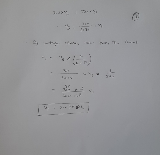
 Determine the voltage v1 in terms of the supply voltage vs for the circuit shown in the figure, where C= 32 D= 712 E= 72 F= 702 C W 112 E A B + w w 4.12 312 01 The voltage vpis Vs.
3. Voltage in RC Circuit For the circuit shown determine the expression for the voltage across...
 3. Voltage in RC Circuit For the circuit shown determine the expression for the voltage across the 1.5 k2 resistor Vy() for 10, then use this expression to find the vx in (V) at time? - 25 ms. Note that the switch opens at: -0. 1kΩ 10 V 1.5 kn 333 F 1=0
Determine the current through R3=50Ω in the circuit shown in (Figure 1), where vs=60V, R1=30Ω, R2=30Ω,...
 Determine the current through R3=50Ω in the circuit shown in
(Figure 1), where vs=60V, R1=30Ω, R2=30Ω, and R4=60Ω. Express your
answer in amperes to three significant figures.
I need both parts A and B please
▼ Part B Determine the current through R3-50 Ω in the circuit shown in Figure 1), where us Rs 60 S2 Express your answer in amperes to three significant figures. Review 60 V. R-30 Ω. R2 30 Ω, and Learning Goal: To determine the voltage,...
Determine the current through R3=50Ω in the circuit shown in
(Figure 1), where vs=60V, R1=30Ω, R2=30Ω, and R4=60Ω. Express your
answer in amperes to three significant figures.
I need both parts A and B please
▼ Part B Determine the current through R3-50 Ω in the circuit shown in Figure 1), where us Rs 60 S2 Express your answer in amperes to three significant figures. Review 60 V. R-30 Ω. R2 30 Ω, and Learning Goal: To determine the voltage,...
USE MATLAB PLEASE Q4) (15 pts) An RLC circuit with an alternating voltage source is shown....
 USE MATLAB PLEASE
Q4) (15 pts) An RLC circuit with an alternating voltage source is shown. The source voltage v, is given by vs = Vm sin(@dt), where on = 21fd, in which fo is the driving frequency. The ampli- tude of the current, 1, in this circuit is given by: Vm I = = R-+[waL-1/(waC)]* where R and C are the resistance of the resistor and capacitance of the capacitor, respectively. For the circuit in the figure C =...
USE MATLAB PLEASE
Q4) (15 pts) An RLC circuit with an alternating voltage source is shown. The source voltage v, is given by vs = Vm sin(@dt), where on = 21fd, in which fo is the driving frequency. The ampli- tude of the current, 1, in this circuit is given by: Vm I = = R-+[waL-1/(waC)]* where R and C are the resistance of the resistor and capacitance of the capacitor, respectively. For the circuit in the figure C =...
Determine the voltage across resistor R2=40ΩR2=40Ω in the circuit shown in (Figure 1), where vs=60Vvs=60V, R1=20ΩR1=20Ω,...
 Determine the voltage across resistor R2=40ΩR2=40Ω in the
circuit shown in (Figure 1), where vs=60Vvs=60V, R1=20ΩR1=20Ω,
R3=30ΩR3=30Ω, and R4=40Ω
Question 6 Part A Determine the voltage across resistor R2 = 40 2 in the circuit shown in (Figure 1), where us = 60 V, R1 = 20 12 R3 = 30 12, and R4 = 40 12 Express your answer in volts to three significant figures. View Available Hint(s) Learning Goal: To determine the voltage, current, and power of circuit...
Determine the voltage across resistor R2=40ΩR2=40Ω in the
circuit shown in (Figure 1), where vs=60Vvs=60V, R1=20ΩR1=20Ω,
R3=30ΩR3=30Ω, and R4=40Ω
Question 6 Part A Determine the voltage across resistor R2 = 40 2 in the circuit shown in (Figure 1), where us = 60 V, R1 = 20 12 R3 = 30 12, and R4 = 40 12 Express your answer in volts to three significant figures. View Available Hint(s) Learning Goal: To determine the voltage, current, and power of circuit...
In the circuit shown in Figure P5 (a). Determine an expression for the output voltage (b)....
 In the circuit shown in Figure P5 (a). Determine an expression for the output voltage (b). Assume si .910 cos(or)+v,). vs 3.1x10cos(v,(), S2 ouut determine the numerical value of, the output voltage. Figure P5.
Determine the output voltage Vo of the circuit shown below. Given Vs = 6V Rs1 =...
 Determine the output voltage Vo of the circuit shown below. Given Vs = 6V Rs1 = 622 RF1 = 51 Rs2 = 31 RF2 = 912 REI Rsi RF2 ww RS2 + Vo VS 오
For the system shown, determine the voltage V, in terms of the resistances and voltage Vi....
 For the system shown, determine the voltage V, in terms of the resistances and voltage Vi. R2 View imiznint
1. Find the expression for the output voltage Vou for the circuit shown below in terms...
 1. Find the expression for the output voltage Vou for the circuit shown below in terms of the resistors Ri, R, R and Rs and the input voltages Vi. V2 and V Calculate Vout when R.-R: = R.-1? and R.-10kfand V, = 4nnV, V,-5mV and V,-6m1V. N3. 2. Find the expression for the output voltage in the circuit shown below and calculate the output voltage Vou where R-R-2.2 k2 and R R-10kQ. V-4 V and V the output voltage when...
b) A periodic voltage vs(t) is applied to a RLC circuit shown in Figure 1 (b)...
 b) A periodic voltage vs(t) is applied to a RLC circuit shown in Figure 1 (b) with R=10012, L=100mH and C=1pF. The first four nonzero terms in the Fourier series is given by the following: v:(t) = 10 +2 sin(10’t)-1sin(2x10't)+sin(3x10°r) v Find the first four nonzero terms in the Fourier series of the steady-state current iſt). (20 marks) R M v.(t) Tv.(t) Figure 2(b): Circuit for Question 2
 Determine the voltage v1 in terms of the supply voltage vs for the circuit shown in the figure, where C= 32 D= 712 E= 72 F= 702 C W 112 E A B + w w 4.12 312 01 The voltage vpis Vs.
 3. Voltage in RC Circuit For the circuit shown determine the expression for the voltage across the 1.5 k2 resistor Vy() for 10, then use this expression to find the vx in (V) at time? - 25 ms. Note that the switch opens at: -0. 1kΩ 10 V 1.5 kn 333 F 1=0
 Determine the current through R3=50Ω in the circuit shown in
(Figure 1), where vs=60V, R1=30Ω, R2=30Ω, and R4=60Ω. Express your
answer in amperes to three significant figures.
I need both parts A and B please
▼ Part B Determine the current through R3-50 Ω in the circuit shown in Figure 1), where us Rs 60 S2 Express your answer in amperes to three significant figures. Review 60 V. R-30 Ω. R2 30 Ω, and Learning Goal: To determine the voltage,...
Determine the current through R3=50Ω in the circuit shown in
(Figure 1), where vs=60V, R1=30Ω, R2=30Ω, and R4=60Ω. Express your
answer in amperes to three significant figures.
I need both parts A and B please
▼ Part B Determine the current through R3-50 Ω in the circuit shown in Figure 1), where us Rs 60 S2 Express your answer in amperes to three significant figures. Review 60 V. R-30 Ω. R2 30 Ω, and Learning Goal: To determine the voltage,...
 USE MATLAB PLEASE
Q4) (15 pts) An RLC circuit with an alternating voltage source is shown. The source voltage v, is given by vs = Vm sin(@dt), where on = 21fd, in which fo is the driving frequency. The ampli- tude of the current, 1, in this circuit is given by: Vm I = = R-+[waL-1/(waC)]* where R and C are the resistance of the resistor and capacitance of the capacitor, respectively. For the circuit in the figure C =...
USE MATLAB PLEASE
Q4) (15 pts) An RLC circuit with an alternating voltage source is shown. The source voltage v, is given by vs = Vm sin(@dt), where on = 21fd, in which fo is the driving frequency. The ampli- tude of the current, 1, in this circuit is given by: Vm I = = R-+[waL-1/(waC)]* where R and C are the resistance of the resistor and capacitance of the capacitor, respectively. For the circuit in the figure C =...
 Determine the voltage across resistor R2=40ΩR2=40Ω in the
circuit shown in (Figure 1), where vs=60Vvs=60V, R1=20ΩR1=20Ω,
R3=30ΩR3=30Ω, and R4=40Ω
Question 6 Part A Determine the voltage across resistor R2 = 40 2 in the circuit shown in (Figure 1), where us = 60 V, R1 = 20 12 R3 = 30 12, and R4 = 40 12 Express your answer in volts to three significant figures. View Available Hint(s) Learning Goal: To determine the voltage, current, and power of circuit...
Determine the voltage across resistor R2=40ΩR2=40Ω in the
circuit shown in (Figure 1), where vs=60Vvs=60V, R1=20ΩR1=20Ω,
R3=30ΩR3=30Ω, and R4=40Ω
Question 6 Part A Determine the voltage across resistor R2 = 40 2 in the circuit shown in (Figure 1), where us = 60 V, R1 = 20 12 R3 = 30 12, and R4 = 40 12 Express your answer in volts to three significant figures. View Available Hint(s) Learning Goal: To determine the voltage, current, and power of circuit...
 In the circuit shown in Figure P5 (a). Determine an expression for the output voltage (b). Assume si .910 cos(or)+v,). vs 3.1x10cos(v,(), S2 ouut determine the numerical value of, the output voltage. Figure P5.
 Determine the output voltage Vo of the circuit shown below. Given Vs = 6V Rs1 = 622 RF1 = 51 Rs2 = 31 RF2 = 912 REI Rsi RF2 ww RS2 + Vo VS 오
 For the system shown, determine the voltage V, in terms of the resistances and voltage Vi. R2 View imiznint
 1. Find the expression for the output voltage Vou for the circuit shown below in terms of the resistors Ri, R, R and Rs and the input voltages Vi. V2 and V Calculate Vout when R.-R: = R.-1? and R.-10kfand V, = 4nnV, V,-5mV and V,-6m1V. N3. 2. Find the expression for the output voltage in the circuit shown below and calculate the output voltage Vou where R-R-2.2 k2 and R R-10kQ. V-4 V and V the output voltage when...
 b) A periodic voltage vs(t) is applied to a RLC circuit shown in Figure 1 (b) with R=10012, L=100mH and C=1pF. The first four nonzero terms in the Fourier series is given by the following: v:(t) = 10 +2 sin(10’t)-1sin(2x10't)+sin(3x10°r) v Find the first four nonzero terms in the Fourier series of the steady-state current iſt). (20 marks) R M v.(t) Tv.(t) Figure 2(b): Circuit for Question 2
Most questions answered within 3 hours.
-
Discuss the benefits of Inventory, Reservation,
& Menu Management Systems. Assuming you are the Manager for...
asked 2 minutes ago -
Which of the following is a concern of the Epic of
Gilgamesh?
human mortality
the destiny...
asked 2 minutes ago -
CONVERT THE FOLLOWING FUNCTION IN MARS SIMULATOR
(MIPS)
This FUNCTION should be Runnable on MARS (MIPS...
asked 8 minutes ago -
Week 8 forum SPHE461
The field of the Fitness Professional includes many
different titles, specialties, certifying...
asked 18 minutes ago -
1. In the short run, the marginal product of labor increases
then decreases because of what?...
asked 1 hour ago -
A farmer wants to compare the tastiness and juiciness of
tomatoes grown with three amounts of...
asked 2 hours ago -
What is facilitated diffusion and how does it differ from
symport and antiport transportation? How do...
asked 2 hours ago -
if a firm producing 100 units at $5.00 each experience
an 80% experience curve, what will...
asked 3 hours ago -
A solid, uniform disk of radius 0.250 m and mass 53.7 kg rolls
down a ramp...
asked 5 hours ago -
Given the following table of high speed internet access vs.
annual home income:
Home Income
%...
asked 6 hours ago -
A baseball batter hits a 0.145kg baseball straight up into the
air. The baseball leaves the...
asked 6 hours ago -
An FM modulator is tested using
single-tone baseband signal with frequency of 50kHz and a sprectrum...
asked 6 hours ago