

You can use any software of your choice
Homework Answers
1. A clock voltage of 8 Vpp is taken and a sc voktage of 4V is taken for providing dc offset.
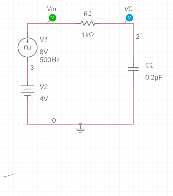
Waveforms-
Initial capacitor voltage = 4V
Final capacitor voltage= 12V
So time constant will be calculated for time required to reach 63% of 4V+( 12-4)V = 4+0.63*8 = 4+5.04V = 9.04V
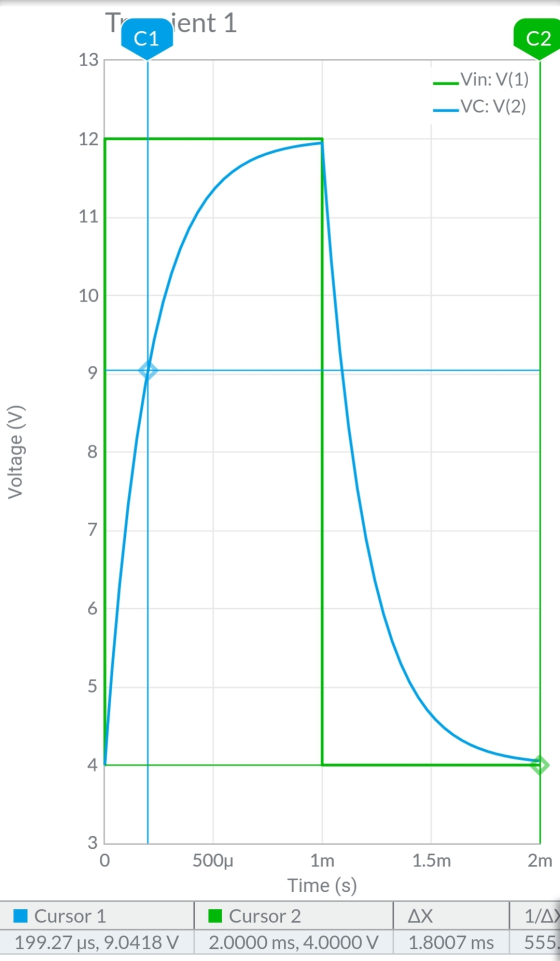
From cursor 1 data time constant = 199 micro sec.
Theoritical time constant = RC = 1k*0.2u
= 0.2msec
= 200micro sec.
2.
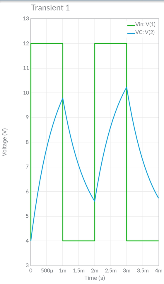
General equation for charging-

Where tau is time constant.
Vo = 8V
Let's check capacitor voltage at t= 200 micro sec.
Vc = 8(1-e^-1)
Vc = 5.05V
Consider dcoffset Vc = 4+5.05 =9.05V
Which matches with graph.
3.
For R =3.9kohm
Time constant will increase so capacitor will charge upto less Voltage than 12V.
Waveform for two cycle-
For C =0.1uF
Time constant further decreases by ten times, capacitor voltage reaches to more than previous case-

RL circuit-
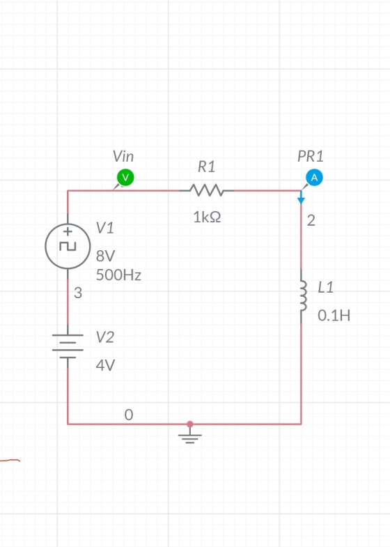
Time constant will be time required for inductor current to reach 9.04A

Time constant= 100 micro sec approx
Theoretically= L/R = 0.1/1k = 100 micro sec.
For R=3.9k

For L=4.7mH(negligible time will be required for steady state reaching)

Add Answer to:
You can use any software of your choice
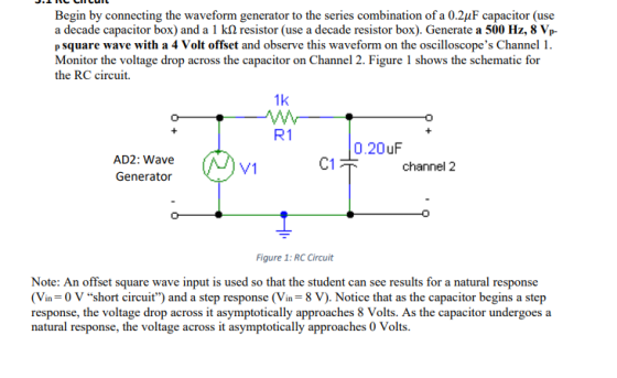
Begin by connecting the waveform generator to the...
Objectives: To learn transient behavior of series RC circuits To observe of time constant and its...
 Objectives: To learn transient behavior of series RC circuits To observe of time constant and its effect on charging process of capacitor using pulse waveforms Equipment: Oscilloscope Function generator Resistors (1 k) Capacitors (1 uF) Breadboard Pre-Lab Questions A pulse is a voltage or current that changes from one level to the other and back again. If a waveform's high time equals its low time, it is called a square wave. The length of each cycle (one positive peak and...
Anything would be help please help me OBJECTIVES Study the behavior of capacitors while charging Learn how changing the...
 Anything would be help please help me
OBJECTIVES Study the behavior of capacitors while charging Learn how changing the values of R or C in a series RC circuit affects the charging time Learn the behavior of capacitor and inductor in a DC circuit 1. 2. 3. EQUIPMENT Breadboard, Multimeter, DC power supply, Oscilloscope, Resistor, Capacitor (values will be provided in lab) Connect the given circuit and notice how the capacitor charges Measure the voltage across the resistor, and across...
Anything would be help please help me
OBJECTIVES Study the behavior of capacitors while charging Learn how changing the values of R or C in a series RC circuit affects the charging time Learn the behavior of capacitor and inductor in a DC circuit 1. 2. 3. EQUIPMENT Breadboard, Multimeter, DC power supply, Oscilloscope, Resistor, Capacitor (values will be provided in lab) Connect the given circuit and notice how the capacitor charges Measure the voltage across the resistor, and across...
it is on a free website, i am just confused on how to build the circuit...
 it
is on a free website, i am just confused on how to build the
circuit
Part 3: RL Circuits: Purpose: Observe the transient current response in an RL circuit. Directions: Using Multisim Live circuit simulator, build an RL (resistor-inductor) series circuit with time constant 5 ms. Use a 5H inductor. You'll have to calculate first the value of the resistor. Using the 'clock voltage' source (this is essentially a square wave function generator), apply an alternating voltage to the...
it
is on a free website, i am just confused on how to build the
circuit
Part 3: RL Circuits: Purpose: Observe the transient current response in an RL circuit. Directions: Using Multisim Live circuit simulator, build an RL (resistor-inductor) series circuit with time constant 5 ms. Use a 5H inductor. You'll have to calculate first the value of the resistor. Using the 'clock voltage' source (this is essentially a square wave function generator), apply an alternating voltage to the...
checking to see if the answers i got are correct and help with the other parts....
 checking to see if the answers i got are correct and help with
the other parts. thank you
Chapter 26 Laboratory Application Assignment In this lab application assignment you will examine an RC coupling circuit and an RC low-pass filter. In the RC coulina circuit you will see how the series capacitor blocks the de component of the input voltage but passes the ac component. In the RC low-pass filter you will see how the low frequencies are passed from...
checking to see if the answers i got are correct and help with
the other parts. thank you
Chapter 26 Laboratory Application Assignment In this lab application assignment you will examine an RC coupling circuit and an RC low-pass filter. In the RC coulina circuit you will see how the series capacitor blocks the de component of the input voltage but passes the ac component. In the RC low-pass filter you will see how the low frequencies are passed from...
Q1: Consider the RC circuit shown below, which is being driven by a function generator supplying...
 Q1: Consider the RC circuit shown below, which is being driven by a function generator supplying a voltage of Vin(t), as shown in the figure next to the circuit Sketch the voltage that would be measured across the 10 microfarad capacitor. Assume that the period of the input square wave is several times longer than the time constant RC. 1 k 2 A voltage KAW function generator 10 MF time
EXPERIMENT 11 STEP RESPONSE TO RC AND RL CIRCUITS pages 11-4 thru 11-7. tep response of the RC an...
 EXPERIMENT 11 STEP RESPONSE TO RC AND RL CIRCUITS pages 11-4 thru 11-7. tep response of the RC and RL circuits is included in OBJECTIVE: O analyze the voltage and current characteristics of a Resistance - Capacitance (RC) circuit when driven by a step voltage function. To analyze the voltage and current characteristics of a Resistance- Inductor (RL) circuit when driven by a step voltage function To design an RC circuit to yield a specified output voltage with a step...
What are the Equilibrium voltages of the capacitor and the resistor when the function generator v...
 What are the Equilibrium voltages of the capacitor and the
resistor when the function generator voltage is +v0? Is this what
you observe on your oscilloscope sketches?
what are the equilibrium voltages of the capacitor and the resistor when the function generator voltage is ± you observe on your oscilloscope sketches? ? Is this what An RC circuit consists of a resistor connected to a capacitor. There may also be a fixed power supply, depending on whether the capacitor is...
What are the Equilibrium voltages of the capacitor and the
resistor when the function generator voltage is +v0? Is this what
you observe on your oscilloscope sketches?
what are the equilibrium voltages of the capacitor and the resistor when the function generator voltage is ± you observe on your oscilloscope sketches? ? Is this what An RC circuit consists of a resistor connected to a capacitor. There may also be a fixed power supply, depending on whether the capacitor is...
Please, answer to the following questions based on the diagram provided. 1)Why is it L/R not LR f...
 Please, answer to the following questions based on the diagram
provided.
1)Why is it L/R not LR for the charging and discharging a series
RL circuit?
2) In the determination of C in part II, what will you obseve if
the voltage probe was connected across decade resistor Rd? Can you
determine capacitance from this? (During the experiment we
connected voltage probes across capacitor)
3) In the determination of L in Part III, what will you obseve
if the voltage...
Please, answer to the following questions based on the diagram
provided.
1)Why is it L/R not LR for the charging and discharging a series
RL circuit?
2) In the determination of C in part II, what will you obseve if
the voltage probe was connected across decade resistor Rd? Can you
determine capacitance from this? (During the experiment we
connected voltage probes across capacitor)
3) In the determination of L in Part III, what will you obseve
if the voltage...
1. Use MultiSim program to simulate the RC circuit shown in Figures 1 using nominal resistor valu...
 1. Use MultiSim program to simulate the RC circuit shown in Figures 1 using nominal resistor value of 100Ω and 10uF capacitor. Set up the function generator for: square wave, frequency 20Hz, duty cycle 50%, offset 1V, and amplitude 1V. Use Tektronix scope to display the input source and the capacitor voltage waveforms on the same display 2. Print out your schematics and print an output showing Channels A and B 3. Use the scope cursors to measure simulated t...
Function Generatr Inductor Model Ra R, Figure 1 Series RLC Circuit Preliminary This laboratory wi...
 Function Generatr Inductor Model Ra R, Figure 1 Series RLC Circuit Preliminary This laboratory will demonstrate how varying resistance changes the natural response of a series RLC circuit (Fig. 1). The function generator is modeled as an ideal voltage source v(t) 5 u() V in series with source resistance Rs-50Q. After measurements using an LCR meter, the inductor is modeled as an ideal L 90 mH inductor in series with resistance RL-20Q. The capacitance is C-0.22 μF. 1) Calculate the...
 Objectives: To learn transient behavior of series RC circuits To observe of time constant and its effect on charging process of capacitor using pulse waveforms Equipment: Oscilloscope Function generator Resistors (1 k) Capacitors (1 uF) Breadboard Pre-Lab Questions A pulse is a voltage or current that changes from one level to the other and back again. If a waveform's high time equals its low time, it is called a square wave. The length of each cycle (one positive peak and...
 Anything would be help please help me
OBJECTIVES Study the behavior of capacitors while charging Learn how changing the values of R or C in a series RC circuit affects the charging time Learn the behavior of capacitor and inductor in a DC circuit 1. 2. 3. EQUIPMENT Breadboard, Multimeter, DC power supply, Oscilloscope, Resistor, Capacitor (values will be provided in lab) Connect the given circuit and notice how the capacitor charges Measure the voltage across the resistor, and across...
Anything would be help please help me
OBJECTIVES Study the behavior of capacitors while charging Learn how changing the values of R or C in a series RC circuit affects the charging time Learn the behavior of capacitor and inductor in a DC circuit 1. 2. 3. EQUIPMENT Breadboard, Multimeter, DC power supply, Oscilloscope, Resistor, Capacitor (values will be provided in lab) Connect the given circuit and notice how the capacitor charges Measure the voltage across the resistor, and across...
 it
is on a free website, i am just confused on how to build the
circuit
Part 3: RL Circuits: Purpose: Observe the transient current response in an RL circuit. Directions: Using Multisim Live circuit simulator, build an RL (resistor-inductor) series circuit with time constant 5 ms. Use a 5H inductor. You'll have to calculate first the value of the resistor. Using the 'clock voltage' source (this is essentially a square wave function generator), apply an alternating voltage to the...
it
is on a free website, i am just confused on how to build the
circuit
Part 3: RL Circuits: Purpose: Observe the transient current response in an RL circuit. Directions: Using Multisim Live circuit simulator, build an RL (resistor-inductor) series circuit with time constant 5 ms. Use a 5H inductor. You'll have to calculate first the value of the resistor. Using the 'clock voltage' source (this is essentially a square wave function generator), apply an alternating voltage to the...
 checking to see if the answers i got are correct and help with
the other parts. thank you
Chapter 26 Laboratory Application Assignment In this lab application assignment you will examine an RC coupling circuit and an RC low-pass filter. In the RC coulina circuit you will see how the series capacitor blocks the de component of the input voltage but passes the ac component. In the RC low-pass filter you will see how the low frequencies are passed from...
checking to see if the answers i got are correct and help with
the other parts. thank you
Chapter 26 Laboratory Application Assignment In this lab application assignment you will examine an RC coupling circuit and an RC low-pass filter. In the RC coulina circuit you will see how the series capacitor blocks the de component of the input voltage but passes the ac component. In the RC low-pass filter you will see how the low frequencies are passed from...
 Q1: Consider the RC circuit shown below, which is being driven by a function generator supplying a voltage of Vin(t), as shown in the figure next to the circuit Sketch the voltage that would be measured across the 10 microfarad capacitor. Assume that the period of the input square wave is several times longer than the time constant RC. 1 k 2 A voltage KAW function generator 10 MF time
 EXPERIMENT 11 STEP RESPONSE TO RC AND RL CIRCUITS pages 11-4 thru 11-7. tep response of the RC and RL circuits is included in OBJECTIVE: O analyze the voltage and current characteristics of a Resistance - Capacitance (RC) circuit when driven by a step voltage function. To analyze the voltage and current characteristics of a Resistance- Inductor (RL) circuit when driven by a step voltage function To design an RC circuit to yield a specified output voltage with a step...
 What are the Equilibrium voltages of the capacitor and the
resistor when the function generator voltage is +v0? Is this what
you observe on your oscilloscope sketches?
what are the equilibrium voltages of the capacitor and the resistor when the function generator voltage is ± you observe on your oscilloscope sketches? ? Is this what An RC circuit consists of a resistor connected to a capacitor. There may also be a fixed power supply, depending on whether the capacitor is...
What are the Equilibrium voltages of the capacitor and the
resistor when the function generator voltage is +v0? Is this what
you observe on your oscilloscope sketches?
what are the equilibrium voltages of the capacitor and the resistor when the function generator voltage is ± you observe on your oscilloscope sketches? ? Is this what An RC circuit consists of a resistor connected to a capacitor. There may also be a fixed power supply, depending on whether the capacitor is...
 Please, answer to the following questions based on the diagram
provided.
1)Why is it L/R not LR for the charging and discharging a series
RL circuit?
2) In the determination of C in part II, what will you obseve if
the voltage probe was connected across decade resistor Rd? Can you
determine capacitance from this? (During the experiment we
connected voltage probes across capacitor)
3) In the determination of L in Part III, what will you obseve
if the voltage...
Please, answer to the following questions based on the diagram
provided.
1)Why is it L/R not LR for the charging and discharging a series
RL circuit?
2) In the determination of C in part II, what will you obseve if
the voltage probe was connected across decade resistor Rd? Can you
determine capacitance from this? (During the experiment we
connected voltage probes across capacitor)
3) In the determination of L in Part III, what will you obseve
if the voltage...
 1. Use MultiSim program to simulate the RC circuit shown in Figures 1 using nominal resistor value of 100Ω and 10uF capacitor. Set up the function generator for: square wave, frequency 20Hz, duty cycle 50%, offset 1V, and amplitude 1V. Use Tektronix scope to display the input source and the capacitor voltage waveforms on the same display 2. Print out your schematics and print an output showing Channels A and B 3. Use the scope cursors to measure simulated t...
 Function Generatr Inductor Model Ra R, Figure 1 Series RLC Circuit Preliminary This laboratory will demonstrate how varying resistance changes the natural response of a series RLC circuit (Fig. 1). The function generator is modeled as an ideal voltage source v(t) 5 u() V in series with source resistance Rs-50Q. After measurements using an LCR meter, the inductor is modeled as an ideal L 90 mH inductor in series with resistance RL-20Q. The capacitance is C-0.22 μF. 1) Calculate the...
Most questions answered within 3 hours.
-
A pebble with mass m is thrown straight up with an initial speed
v0 so that...
asked 2 minutes ago -
Let X be a discrete random variable that follows a
binomial distribution with n = 11...
asked 11 minutes ago -
The equilibrium constant, K, for the following reaction is
1.29×10⁻² at 600
K.
COCl2(g) --->
CO(g)...
asked 24 minutes ago -
It is known that 72% of people have a favorable opinion of their
local police force....
asked 27 minutes ago -
A vertical straight wire carrying an upward 26-A current exerts
an attractive force per unit length...
asked 40 minutes ago -
For the purposes of this assignment, you are to choose an
adaptive trait common to more...
asked 48 minutes ago -
Two identical flutes can play middle C (262 Hz) at 20◦C. How
many beats per second...
asked 56 minutes ago -
Potassium phosphate and calcium chloride react in a double
replacement reaction. To produce 1.0 moles of...
asked 51 minutes ago -
Sparky, Co. purchased land as a factory site for $600,000.
Sparky paid $42,000 to tear down...
asked 1 hour ago -
A Chi-square distribution with 14 degrees of freedom is a
correct model for
Question 8 options:...
asked 1 hour ago -
In a group of 45 mice, there are 10 that have a certain genetic
character. suppose...
asked 1 hour ago -
Topic: Hydrogenic Atoms
The wavefunction of one of the d orbitals is proportional to sin
θ...
asked 1 hour ago