


Homework Answers
All the pats has been solved and solution has been attached.

Add Answer to:
Learning Goal: To analyze and design a passive, first-order low- pass filter using a series RL...
Learning Goal: To analyze and design a passive, first-order low-pass filter using a series RL circuit....
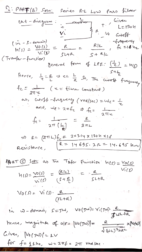
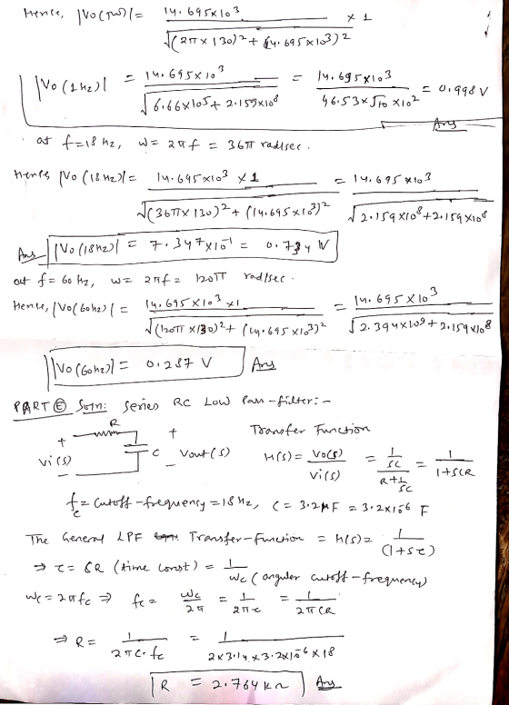
 Learning Goal: To analyze and design a passive, first-order low-pass filter using a series RL circuit. The analysis and design will be repeated for a series RC circuit. An electrocardiogram needs to detect periodic signals of approximately 1 Hz (since the resting heart rate of a healthy adult is between 55 and 70 beats per minute). The instrument operates in an electrical environment that is very noisy with a frequency of 60 Hz. It is desirable to have a low-pass...
Part B - Designing and analyzing a series RC high-pass filter Using the available 3.2 uF...
 Part B - Designing and analyzing a series RC high-pass filter Using the available 3.2 uF capacitor, what is the value of the resistor needed to make a high-pass filter with a cutoff frequency of 2800 Hz? Express your answer to three significant figures and include appropriate units. View Available Hint(s) НА ? R = Value Units Submit Part C - Measuring the effectiveness of the series RC high-pass filter To measure the effectiveness of the design, find the magnitude...
Learning Goal: To analyze and design a passive, second-order bandpass filter using a series RLC circuit....
 Learning Goal: To analyze and design a passive, second-order bandpass filter using a series RLC circuit. A bandpass filter is needed for an equalizer, a device that allows one to select the level of amplification of sounds within a specific frequency band while not affecting the sounds outside that band. The filter should block frequencies lower than 1.8 kHz and have a resonant frequency of 5.4 kHz A 3.2 AF capacitor and any needed resistors and inductors are available to...
Analysis and Design of High-Pass Filters 2 of 3 Learning Goal: To analyze and design a...
 Analysis and Design of High-Pass Filters 2 of 3 Learning Goal: To analyze and design a passive, first-order high-pass filter using a series RC circut An instrument needs to detect periodic signals of approximately 5000 H. The instrument operates in an environment with a lot of periodienos ranging from a few to several hundred hert. A high-pass RC ter can be built using available 32 capacitors, resistors of any necessary value are also available Part A Qualitative analysis of a...
Analysis and Design of Low Pass Filters 1 of 3 > Before designing the throne must...
 Analysis and Design of Low Pass Filters 1 of 3 > Before designing the throne must understand the relationship between the output voltage of the circut and the frequency. For a series RL crout, how do the impedances of the circut elements depend on the frequency? Select the correct answer View Available Hintſ Learning Goal: To analyze and design a passive, first-order low-pass filter using a series RL rout. The analysis and design will be repeated for a series RC...
Analyals and Deaign of High-Pass Filters O 5o 14 > I Review I Corstante Learning Goal:...
 Analyals and Deaign of High-Pass Filters O 5o 14 > I Review I Corstante Learning Goal: To analyze and design a passive, first-order high-pass titer using a series RC arcuit. • Part A-Qualtative analysis of a series RC low-pess fiher An instrument nceds to detect penodio signals ot approximately 5O00 Hz. The instrument operates in an environment with a lot ot periodic noise ranging trom a few to several hundrod hertz. Ahigh-pass RC titer can be bult using avalable 2.5...
Part B Using C = 26 nF capacitors, design an active broadband first-order bandreject filter with...
 Part B Using C = 26 nF capacitors, design an active broadband first-order bandreject filter with a lower cutoff frequency of 400 Hz, an upper cutoff frequency of 4000 Hz, and a passband gain of 0 dB. Determine value of resistance in the high-pass filter RH. Express your answer to three significant figures and include the appropriate units. RH = Value Units Submit Request Answer Part C Determine value of resistance in the low-pass filter RL Express your answer to...
Problem 15 15 of 21 > A Review Constants Using 2.7 K resistors and ideal op...
 Problem 15 15 of 21 > A Review Constants Using 2.7 K resistors and ideal op amps, design a circuit that will implement the low-pass Butterworth filter having a cutoll frequency of 600 Hz and the gain of no more than-32 dB at 2500 Hz. The gain in the passband is one Part A Determine the order of the low-pass Butterworth filter with given filter specifications. Express your answer as an integer. IVO AX t ? 11 = Submit Request...
Pre-Problem: Design a simple first-order low pass filter with a cutoff frequency of 1250Hz (that is,...
Pre-Problem: Design a simple first-order low pass filter with a cutoff frequency of 1250Hz (that is, choose resistorand capacitor values for an RC circuit). Plot the filter’s magnitude response to prove that yourfilter is properly designed.
QUESTION 1 Design a second order passive low-pass filter that has a cutoff frequency of 6...
 QUESTION 1 Design a second order passive low-pass filter that has a cutoff frequency of 6 KHz by: a. Choosing an appropriate R and C value. (HINT: R1=R2=10K and C1=C2=C) A= C/S V=J/C V=AN 1 H2 = 1/5 F = CN Final Solution: C1=
 Learning Goal: To analyze and design a passive, first-order low-pass filter using a series RL circuit. The analysis and design will be repeated for a series RC circuit. An electrocardiogram needs to detect periodic signals of approximately 1 Hz (since the resting heart rate of a healthy adult is between 55 and 70 beats per minute). The instrument operates in an electrical environment that is very noisy with a frequency of 60 Hz. It is desirable to have a low-pass...
 Part B - Designing and analyzing a series RC high-pass filter Using the available 3.2 uF capacitor, what is the value of the resistor needed to make a high-pass filter with a cutoff frequency of 2800 Hz? Express your answer to three significant figures and include appropriate units. View Available Hint(s) НА ? R = Value Units Submit Part C - Measuring the effectiveness of the series RC high-pass filter To measure the effectiveness of the design, find the magnitude...
 Learning Goal: To analyze and design a passive, second-order bandpass filter using a series RLC circuit. A bandpass filter is needed for an equalizer, a device that allows one to select the level of amplification of sounds within a specific frequency band while not affecting the sounds outside that band. The filter should block frequencies lower than 1.8 kHz and have a resonant frequency of 5.4 kHz A 3.2 AF capacitor and any needed resistors and inductors are available to...
 Analysis and Design of High-Pass Filters 2 of 3 Learning Goal: To analyze and design a passive, first-order high-pass filter using a series RC circut An instrument needs to detect periodic signals of approximately 5000 H. The instrument operates in an environment with a lot of periodienos ranging from a few to several hundred hert. A high-pass RC ter can be built using available 32 capacitors, resistors of any necessary value are also available Part A Qualitative analysis of a...
 Analysis and Design of Low Pass Filters 1 of 3 > Before designing the throne must understand the relationship between the output voltage of the circut and the frequency. For a series RL crout, how do the impedances of the circut elements depend on the frequency? Select the correct answer View Available Hintſ Learning Goal: To analyze and design a passive, first-order low-pass filter using a series RL rout. The analysis and design will be repeated for a series RC...
 Analyals and Deaign of High-Pass Filters O 5o 14 > I Review I Corstante Learning Goal: To analyze and design a passive, first-order high-pass titer using a series RC arcuit. • Part A-Qualtative analysis of a series RC low-pess fiher An instrument nceds to detect penodio signals ot approximately 5O00 Hz. The instrument operates in an environment with a lot ot periodic noise ranging trom a few to several hundrod hertz. Ahigh-pass RC titer can be bult using avalable 2.5...
 Part B Using C = 26 nF capacitors, design an active broadband first-order bandreject filter with a lower cutoff frequency of 400 Hz, an upper cutoff frequency of 4000 Hz, and a passband gain of 0 dB. Determine value of resistance in the high-pass filter RH. Express your answer to three significant figures and include the appropriate units. RH = Value Units Submit Request Answer Part C Determine value of resistance in the low-pass filter RL Express your answer to...
 Problem 15 15 of 21 > A Review Constants Using 2.7 K resistors and ideal op amps, design a circuit that will implement the low-pass Butterworth filter having a cutoll frequency of 600 Hz and the gain of no more than-32 dB at 2500 Hz. The gain in the passband is one Part A Determine the order of the low-pass Butterworth filter with given filter specifications. Express your answer as an integer. IVO AX t ? 11 = Submit Request...
 QUESTION 1 Design a second order passive low-pass filter that has a cutoff frequency of 6 KHz by: a. Choosing an appropriate R and C value. (HINT: R1=R2=10K and C1=C2=C) A= C/S V=J/C V=AN 1 H2 = 1/5 F = CN Final Solution: C1=
Most questions answered within 3 hours.
-
Using MARS simulator, write MIPS programs according to
the following scenarios: Receive a positive integer number...
asked 1 hour ago -
An object in front of a concave mirror has a real image that is
11.5 cm...
asked 1 hour ago -
Consider the reaction, C3 H8 + O2 --> CO2 + H2O. How many
moles of O2...
asked 3 hours ago -
You and your opponent both roll a fair die. If you both roll the
same number,...
asked 3 hours ago -
In a study of the accuracy of fast food drive-through orders,
Restaurant A had 257 accurate...
asked 3 hours ago -
Identify and describe in detail the four categories of
institutions that could be included in a...
asked 3 hours ago -
In python
class Customer:
def __init__(self, customer_id, last_name, first_name, phone_number, address):
self._customer_id = int(customer_id)
self._last_name =...
asked 4 hours ago -
What is an example of a limitation in implementing a new
ERP system and how it...
asked 4 hours ago -
In a section of 9.7cm of an artery with a radius of 2.6mm there
is a...
asked 4 hours ago -
the two carboxylic acid groups of aspartic acid have different
acidities with pKa values of 2.1...
asked 4 hours ago -
Would CuCO3 aqueous salt combined with calcium chloride
form a solid precipitate? If so, what would...
asked 4 hours ago -
How do ECM Solutions assist in embedding a culture of continuous
improvement in an organization? (Project...
asked 4 hours ago