


Homework Answers


Add Answer to:
Analysis and Design of Low Pass Filters 1 of 3 > Before designing the throne must...
Analysis and Design of High-Pass Filters 2 of 3 Learning Goal: To analyze and design a...
 Analysis and Design of High-Pass Filters 2 of 3 Learning Goal: To analyze and design a passive, first-order high-pass filter using a series RC circut An instrument needs to detect periodic signals of approximately 5000 H. The instrument operates in an environment with a lot of periodienos ranging from a few to several hundred hert. A high-pass RC ter can be built using available 32 capacitors, resistors of any necessary value are also available Part A Qualitative analysis of a...
Learning Goal: To analyze and design a passive, first-order low- pass filter using a series RL...
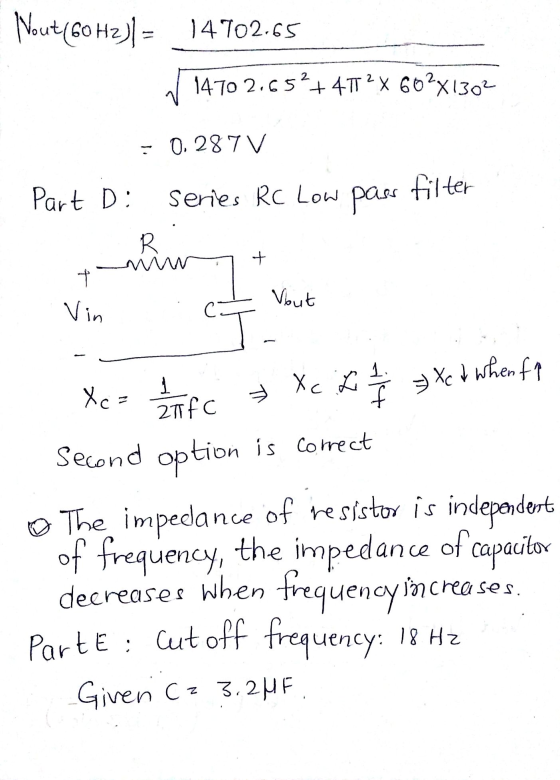
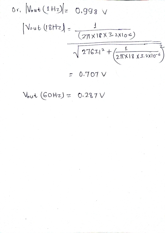
 Learning Goal: To analyze and design a passive, first-order low- pass filter using a series RL circuit. The analysis and design will be repeated for a series RC circuit. An electrocardiogram needs to detect periodic signals of approximately 1 Hz (since the resting heart rate of a healthy adult is between 55 and 70 beats per minute). The instrument operates in an electrical environment that is very noisy with a frequency of 60 Hz. It is desirable to have a...
Learning Goal: To analyze and design a passive, first-order low-pass filter using a series RL circuit....
 Learning Goal: To analyze and design a passive, first-order low-pass filter using a series RL circuit. The analysis and design will be repeated for a series RC circuit. An electrocardiogram needs to detect periodic signals of approximately 1 Hz (since the resting heart rate of a healthy adult is between 55 and 70 beats per minute). The instrument operates in an electrical environment that is very noisy with a frequency of 60 Hz. It is desirable to have a low-pass...
Analyals and Deaign of High-Pass Filters O 5o 14 > I Review I Corstante Learning Goal:...
 Analyals and Deaign of High-Pass Filters O 5o 14 > I Review I Corstante Learning Goal: To analyze and design a passive, first-order high-pass titer using a series RC arcuit. • Part A-Qualtative analysis of a series RC low-pess fiher An instrument nceds to detect penodio signals ot approximately 5O00 Hz. The instrument operates in an environment with a lot ot periodic noise ranging trom a few to several hundrod hertz. Ahigh-pass RC titer can be bult using avalable 2.5...
Part B - Designing and analyzing a series RC high-pass filter Using the available 3.2 uF...
 Part B - Designing and analyzing a series RC high-pass filter Using the available 3.2 uF capacitor, what is the value of the resistor needed to make a high-pass filter with a cutoff frequency of 2800 Hz? Express your answer to three significant figures and include appropriate units. View Available Hint(s) НА ? R = Value Units Submit Part C - Measuring the effectiveness of the series RC high-pass filter To measure the effectiveness of the design, find the magnitude...
C, V. Low-pass High-pass Procedure: Design the following filters and be certain to provide the co...
 C, V. Low-pass High-pass Procedure: Design the following filters and be certain to provide the component values you used in a table like those shown on the third page. Record your calculations because they will be requested in the lab report. To make the lab simpler let the input resistor Ri be the same for all stages. In this particular case the loading effects from cascading the op-amp circuits will have little influence on the overall gain. Refer to your...
A) Design a low - pass filter with a -3dB frequency equal to the four digits...
 A) Design a low - pass filter with a -3dB frequency equal to the four digits of your birth month and day (in Hz). Choose a reasonable value for your capacitor or inductor. 4. B) Give an example that you prefer a 1X over a 10X probe to measure the voltage of acircuiit hode. C)What is the value of a precision resistor with the code 4321F?
10 Design a low pass filter using a resistor R and a capacitor C of 0.2uF....
 10 Design a low pass filter using a resistor R and a capacitor C of 0.2uF. Sketch the circuit diagram, mark thoe output voltage Vo, calculate the resistance value for R if 3dB frequency is 2500 Hz, and write out the voltage gain vs ω (for both magnitude and phase). Repeat the design if R is given as 30 Ohm and C is unknown.
RC Circuit Design a passive, low-pass filter with corner frequency around 400 Hz and input impedance...
 RC Circuit
Design a passive, low-pass filter with corner frequency around 400 Hz and input impedance of at least 1k2. Ģive the component values and compute the magnitude of the output impedance at 100 Hz.
RC Circuit
Design a passive, low-pass filter with corner frequency around 400 Hz and input impedance of at least 1k2. Ģive the component values and compute the magnitude of the output impedance at 100 Hz.
For the low-pass filter circuit shown in Fig 2 3k Ω 200mil in out Fig 2 3.a. Use a 2.2nF capacitor to design a high-pas...
 For the low-pass filter circuit shown in Fig 2 3k Ω 200mil in out Fig 2 3.a. Use a 2.2nF capacitor to design a high-pass filter to have a cutoff frequency of Skn Draw a schematic of your design. Show all component values and voltages c. Sketch the frequency response of the voltage gain and phase shift Magnitude dB Frequency Hz Phase Frequency Hz
For the low-pass filter circuit shown in Fig 2 3k Ω 200mil in out Fig 2...
For the low-pass filter circuit shown in Fig 2 3k Ω 200mil in out Fig 2 3.a. Use a 2.2nF capacitor to design a high-pass filter to have a cutoff frequency of Skn Draw a schematic of your design. Show all component values and voltages c. Sketch the frequency response of the voltage gain and phase shift Magnitude dB Frequency Hz Phase Frequency Hz
For the low-pass filter circuit shown in Fig 2 3k Ω 200mil in out Fig 2...
 Analysis and Design of High-Pass Filters 2 of 3 Learning Goal: To analyze and design a passive, first-order high-pass filter using a series RC circut An instrument needs to detect periodic signals of approximately 5000 H. The instrument operates in an environment with a lot of periodienos ranging from a few to several hundred hert. A high-pass RC ter can be built using available 32 capacitors, resistors of any necessary value are also available Part A Qualitative analysis of a...
 Learning Goal: To analyze and design a passive, first-order low- pass filter using a series RL circuit. The analysis and design will be repeated for a series RC circuit. An electrocardiogram needs to detect periodic signals of approximately 1 Hz (since the resting heart rate of a healthy adult is between 55 and 70 beats per minute). The instrument operates in an electrical environment that is very noisy with a frequency of 60 Hz. It is desirable to have a...
 Learning Goal: To analyze and design a passive, first-order low-pass filter using a series RL circuit. The analysis and design will be repeated for a series RC circuit. An electrocardiogram needs to detect periodic signals of approximately 1 Hz (since the resting heart rate of a healthy adult is between 55 and 70 beats per minute). The instrument operates in an electrical environment that is very noisy with a frequency of 60 Hz. It is desirable to have a low-pass...
 Analyals and Deaign of High-Pass Filters O 5o 14 > I Review I Corstante Learning Goal: To analyze and design a passive, first-order high-pass titer using a series RC arcuit. • Part A-Qualtative analysis of a series RC low-pess fiher An instrument nceds to detect penodio signals ot approximately 5O00 Hz. The instrument operates in an environment with a lot ot periodic noise ranging trom a few to several hundrod hertz. Ahigh-pass RC titer can be bult using avalable 2.5...
 Part B - Designing and analyzing a series RC high-pass filter Using the available 3.2 uF capacitor, what is the value of the resistor needed to make a high-pass filter with a cutoff frequency of 2800 Hz? Express your answer to three significant figures and include appropriate units. View Available Hint(s) НА ? R = Value Units Submit Part C - Measuring the effectiveness of the series RC high-pass filter To measure the effectiveness of the design, find the magnitude...
 C, V. Low-pass High-pass Procedure: Design the following filters and be certain to provide the component values you used in a table like those shown on the third page. Record your calculations because they will be requested in the lab report. To make the lab simpler let the input resistor Ri be the same for all stages. In this particular case the loading effects from cascading the op-amp circuits will have little influence on the overall gain. Refer to your...
 A) Design a low - pass filter with a -3dB frequency equal to the four digits of your birth month and day (in Hz). Choose a reasonable value for your capacitor or inductor. 4. B) Give an example that you prefer a 1X over a 10X probe to measure the voltage of acircuiit hode. C)What is the value of a precision resistor with the code 4321F?
 10 Design a low pass filter using a resistor R and a capacitor C of 0.2uF. Sketch the circuit diagram, mark thoe output voltage Vo, calculate the resistance value for R if 3dB frequency is 2500 Hz, and write out the voltage gain vs ω (for both magnitude and phase). Repeat the design if R is given as 30 Ohm and C is unknown.
 RC Circuit
Design a passive, low-pass filter with corner frequency around 400 Hz and input impedance of at least 1k2. Ģive the component values and compute the magnitude of the output impedance at 100 Hz.
RC Circuit
Design a passive, low-pass filter with corner frequency around 400 Hz and input impedance of at least 1k2. Ģive the component values and compute the magnitude of the output impedance at 100 Hz.
 For the low-pass filter circuit shown in Fig 2 3k Ω 200mil in out Fig 2 3.a. Use a 2.2nF capacitor to design a high-pass filter to have a cutoff frequency of Skn Draw a schematic of your design. Show all component values and voltages c. Sketch the frequency response of the voltage gain and phase shift Magnitude dB Frequency Hz Phase Frequency Hz
For the low-pass filter circuit shown in Fig 2 3k Ω 200mil in out Fig 2...
For the low-pass filter circuit shown in Fig 2 3k Ω 200mil in out Fig 2 3.a. Use a 2.2nF capacitor to design a high-pass filter to have a cutoff frequency of Skn Draw a schematic of your design. Show all component values and voltages c. Sketch the frequency response of the voltage gain and phase shift Magnitude dB Frequency Hz Phase Frequency Hz
For the low-pass filter circuit shown in Fig 2 3k Ω 200mil in out Fig 2...
Most questions answered within 3 hours.
-
Discuss graph representation, Breadth-first search and
Depth-first search. Use examples to highlight pros and
cons.
asked 5 minutes ago -
what are the impacts of droughts in east Africa on the:
1) economy:
2) agriculture:
3)...
asked 7 minutes ago -
Fleas can jump quite high; experiments show that they can reach
an altitude of 120 times...
asked 13 minutes ago -
The rate constant for this first-order reaction is 0.0520 s–1 at
400 °C.
A----> Product
After...
asked 19 minutes ago -
boolean a = ( true && false );
System.out.println( a );
what is the output of...
asked 23 minutes ago -
NEED HELP ASAP PLEASE! (I already answered 1-4)
The comparative financial statements of Marshall Inc. are...
asked 29 minutes ago -
PLEASE RESPOND TO POST. DO YOU AGREE OR DISAGREE? IF SO WHY.The
five traditional intelligence collection...
asked 29 minutes ago -
Grandma Assignment: This was my previous professor’s son’s
fourth grade homework assign- ment. Maxine, Mabel, Mavis,...
asked 30 minutes ago -
Write the pseudocode below as a working Python program.
Take a screenshot of your code and...
asked 45 minutes ago -
Calculate the concentrations of all species in a 0.810 M
Na2SO30.810 M Na2SO3 (sodium sulfite) solution....
asked 52 minutes ago -
Deciding Whether to Use Flexible Staffing
The Kaiser Manufacturing Com pany (KMC) has been in existence...
asked 42 minutes ago -
True or False for the following statement:
All of the B cells in your body right...
asked 50 minutes ago