
Homework Answers

Please upvote if answer is helpful
Add Answer to:
C, V. Low-pass High-pass Procedure: Design the following filters and be certain to provide the co...
Active Low-pass and High-pass Filters for Crossover Circuitry (PSPICE) Design a first order active high-pass filter...
 Active Low-pass and High-pass Filters for Crossover Circuitry
(PSPICE)
Design a first order active high-pass filter with cut-off
frequency of 1 kHz & gain 20dB.
Design a first order active low-pass filter with cut-off
frequency of 1 kHz & gain 20dB.
Plot the magnitude and phase responses of the active high-pass
and low-pass filters you have designed using PSpice (Use UA741 Op
amp and ±12V dual supply).
Connect your active low-pass and high-pass filters as shown in
Fig. 1-b. Assume...
Active Low-pass and High-pass Filters for Crossover Circuitry
(PSPICE)
Design a first order active high-pass filter with cut-off
frequency of 1 kHz & gain 20dB.
Design a first order active low-pass filter with cut-off
frequency of 1 kHz & gain 20dB.
Plot the magnitude and phase responses of the active high-pass
and low-pass filters you have designed using PSpice (Use UA741 Op
amp and ±12V dual supply).
Connect your active low-pass and high-pass filters as shown in
Fig. 1-b. Assume...
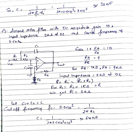
Design a second-order Butterworth low-pass filter with a DC gain of 0 dB and a -3...
Design a second-order Butterworth low-pass filter with a DC gain of 0 dB and a -3 dB frequency of 5.24 kHz. (include circuit design w/ component values)
RC Circuit Design a passive, low-pass filter with corner frequency around 400 Hz and input impedance...
 RC Circuit
Design a passive, low-pass filter with corner frequency around 400 Hz and input impedance of at least 1k2. Ģive the component values and compute the magnitude of the output impedance at 100 Hz.
RC Circuit
Design a passive, low-pass filter with corner frequency around 400 Hz and input impedance of at least 1k2. Ģive the component values and compute the magnitude of the output impedance at 100 Hz.
Analysis and Design of High-Pass Filters 2 of 3 Learning Goal: To analyze and design a...
 Analysis and Design of High-Pass Filters 2 of 3 Learning Goal: To analyze and design a passive, first-order high-pass filter using a series RC circut An instrument needs to detect periodic signals of approximately 5000 H. The instrument operates in an environment with a lot of periodienos ranging from a few to several hundred hert. A high-pass RC ter can be built using available 32 capacitors, resistors of any necessary value are also available Part A Qualitative analysis of a...
Determine the transfer function for a 2nd order Chebyshev low pass filter with 3dB frequency of...
 Determine the transfer function for a 2nd order Chebyshev low pass filter with 3dB frequency of 100krad/sec, a maximum gain of OdB, and a passband ripple of 1dB. (40 points) (a) (b) A bandpass filter is made by cascading the filter described in part (a) with a 2nd order Chebyshev high pass filter with 3dB frequency of 1krad/sec, a maximum gain of OdB and passband ripple of 2dB. Determine the midband gain of the filter. (30 points) A Chebyshev bandpass...
200 HZ. 6.25) Design a cascading LC low-pass filter with maxi- mally flat magnitude response. Use a passband of 0 to...
 200 HZ. 6.25) Design a cascading LC low-pass filter with maxi- mally flat magnitude response. Use a passband of 0 to 5 kHz with 5 kHz cutoff frequency and filter to attenuate all frequencies at and above 10 kHz by at least 30 dB. Use R R1 = 50 2
200 HZ. 6.25) Design a cascading LC low-pass filter with maxi- mally flat magnitude response. Use a passband of 0 to 5 kHz with 5 kHz cutoff frequency and filter...
200 HZ. 6.25) Design a cascading LC low-pass filter with maxi- mally flat magnitude response. Use a passband of 0 to 5 kHz with 5 kHz cutoff frequency and filter to attenuate all frequencies at and above 10 kHz by at least 30 dB. Use R R1 = 50 2
200 HZ. 6.25) Design a cascading LC low-pass filter with maxi- mally flat magnitude response. Use a passband of 0 to 5 kHz with 5 kHz cutoff frequency and filter...
What is the answer to question 23.1? 23.1 Active low-pass filter You can make a low-pass...
 What is the answer to question
23.1?
23.1 Active low-pass filter You can make a low-pass filter by putting a capacitor Cr and resistor Rf in parallel for Zj as shown in Figure 23.1. At low frequencies (well below the corner frequency), the feedback impedance is approximately Rf and the gain of a non-inverting amplifier is is 1 +R//R,. At high frequencies (well above the corner frequency),the impedance is approx- imately 1/(jwCs), and the gain of a non-inverting amplifier is...
What is the answer to question
23.1?
23.1 Active low-pass filter You can make a low-pass filter by putting a capacitor Cr and resistor Rf in parallel for Zj as shown in Figure 23.1. At low frequencies (well below the corner frequency), the feedback impedance is approximately Rf and the gain of a non-inverting amplifier is is 1 +R//R,. At high frequencies (well above the corner frequency),the impedance is approx- imately 1/(jwCs), and the gain of a non-inverting amplifier is...
Analysis and Design of Low Pass Filters 1 of 3 > Before designing the throne must...
 Analysis and Design of Low Pass Filters 1 of 3 > Before designing the throne must understand the relationship between the output voltage of the circut and the frequency. For a series RL crout, how do the impedances of the circut elements depend on the frequency? Select the correct answer View Available Hintſ Learning Goal: To analyze and design a passive, first-order low-pass filter using a series RL rout. The analysis and design will be repeated for a series RC...
For the low-pass filter circuit shown in Fig 2 3k Ω 200mil in out Fig 2 3.a. Use a 2.2nF capacitor to design a high-pas...
 For the low-pass filter circuit shown in Fig 2 3k Ω 200mil in out Fig 2 3.a. Use a 2.2nF capacitor to design a high-pass filter to have a cutoff frequency of Skn Draw a schematic of your design. Show all component values and voltages c. Sketch the frequency response of the voltage gain and phase shift Magnitude dB Frequency Hz Phase Frequency Hz
For the low-pass filter circuit shown in Fig 2 3k Ω 200mil in out Fig 2...
For the low-pass filter circuit shown in Fig 2 3k Ω 200mil in out Fig 2 3.a. Use a 2.2nF capacitor to design a high-pass filter to have a cutoff frequency of Skn Draw a schematic of your design. Show all component values and voltages c. Sketch the frequency response of the voltage gain and phase shift Magnitude dB Frequency Hz Phase Frequency Hz
For the low-pass filter circuit shown in Fig 2 3k Ω 200mil in out Fig 2...
 Active Low-pass and High-pass Filters for Crossover Circuitry
(PSPICE)
Design a first order active high-pass filter with cut-off
frequency of 1 kHz & gain 20dB.
Design a first order active low-pass filter with cut-off
frequency of 1 kHz & gain 20dB.
Plot the magnitude and phase responses of the active high-pass
and low-pass filters you have designed using PSpice (Use UA741 Op
amp and ±12V dual supply).
Connect your active low-pass and high-pass filters as shown in
Fig. 1-b. Assume...
Active Low-pass and High-pass Filters for Crossover Circuitry
(PSPICE)
Design a first order active high-pass filter with cut-off
frequency of 1 kHz & gain 20dB.
Design a first order active low-pass filter with cut-off
frequency of 1 kHz & gain 20dB.
Plot the magnitude and phase responses of the active high-pass
and low-pass filters you have designed using PSpice (Use UA741 Op
amp and ±12V dual supply).
Connect your active low-pass and high-pass filters as shown in
Fig. 1-b. Assume...
 RC Circuit
Design a passive, low-pass filter with corner frequency around 400 Hz and input impedance of at least 1k2. Ģive the component values and compute the magnitude of the output impedance at 100 Hz.
RC Circuit
Design a passive, low-pass filter with corner frequency around 400 Hz and input impedance of at least 1k2. Ģive the component values and compute the magnitude of the output impedance at 100 Hz.
 Analysis and Design of High-Pass Filters 2 of 3 Learning Goal: To analyze and design a passive, first-order high-pass filter using a series RC circut An instrument needs to detect periodic signals of approximately 5000 H. The instrument operates in an environment with a lot of periodienos ranging from a few to several hundred hert. A high-pass RC ter can be built using available 32 capacitors, resistors of any necessary value are also available Part A Qualitative analysis of a...
 Determine the transfer function for a 2nd order Chebyshev low pass filter with 3dB frequency of 100krad/sec, a maximum gain of OdB, and a passband ripple of 1dB. (40 points) (a) (b) A bandpass filter is made by cascading the filter described in part (a) with a 2nd order Chebyshev high pass filter with 3dB frequency of 1krad/sec, a maximum gain of OdB and passband ripple of 2dB. Determine the midband gain of the filter. (30 points) A Chebyshev bandpass...
 200 HZ. 6.25) Design a cascading LC low-pass filter with maxi- mally flat magnitude response. Use a passband of 0 to 5 kHz with 5 kHz cutoff frequency and filter to attenuate all frequencies at and above 10 kHz by at least 30 dB. Use R R1 = 50 2
200 HZ. 6.25) Design a cascading LC low-pass filter with maxi- mally flat magnitude response. Use a passband of 0 to 5 kHz with 5 kHz cutoff frequency and filter...
200 HZ. 6.25) Design a cascading LC low-pass filter with maxi- mally flat magnitude response. Use a passband of 0 to 5 kHz with 5 kHz cutoff frequency and filter to attenuate all frequencies at and above 10 kHz by at least 30 dB. Use R R1 = 50 2
200 HZ. 6.25) Design a cascading LC low-pass filter with maxi- mally flat magnitude response. Use a passband of 0 to 5 kHz with 5 kHz cutoff frequency and filter...
 What is the answer to question
23.1?
23.1 Active low-pass filter You can make a low-pass filter by putting a capacitor Cr and resistor Rf in parallel for Zj as shown in Figure 23.1. At low frequencies (well below the corner frequency), the feedback impedance is approximately Rf and the gain of a non-inverting amplifier is is 1 +R//R,. At high frequencies (well above the corner frequency),the impedance is approx- imately 1/(jwCs), and the gain of a non-inverting amplifier is...
What is the answer to question
23.1?
23.1 Active low-pass filter You can make a low-pass filter by putting a capacitor Cr and resistor Rf in parallel for Zj as shown in Figure 23.1. At low frequencies (well below the corner frequency), the feedback impedance is approximately Rf and the gain of a non-inverting amplifier is is 1 +R//R,. At high frequencies (well above the corner frequency),the impedance is approx- imately 1/(jwCs), and the gain of a non-inverting amplifier is...
 Analysis and Design of Low Pass Filters 1 of 3 > Before designing the throne must understand the relationship between the output voltage of the circut and the frequency. For a series RL crout, how do the impedances of the circut elements depend on the frequency? Select the correct answer View Available Hintſ Learning Goal: To analyze and design a passive, first-order low-pass filter using a series RL rout. The analysis and design will be repeated for a series RC...
 For the low-pass filter circuit shown in Fig 2 3k Ω 200mil in out Fig 2 3.a. Use a 2.2nF capacitor to design a high-pass filter to have a cutoff frequency of Skn Draw a schematic of your design. Show all component values and voltages c. Sketch the frequency response of the voltage gain and phase shift Magnitude dB Frequency Hz Phase Frequency Hz
For the low-pass filter circuit shown in Fig 2 3k Ω 200mil in out Fig 2...
For the low-pass filter circuit shown in Fig 2 3k Ω 200mil in out Fig 2 3.a. Use a 2.2nF capacitor to design a high-pass filter to have a cutoff frequency of Skn Draw a schematic of your design. Show all component values and voltages c. Sketch the frequency response of the voltage gain and phase shift Magnitude dB Frequency Hz Phase Frequency Hz
For the low-pass filter circuit shown in Fig 2 3k Ω 200mil in out Fig 2...
Most questions answered within 3 hours.
-
(a) A piston at 6.1 atm contains a gas that occupies a volume of
3.5 L....
asked 1 hour ago -
Please answer true or false. Words
cannot be changed or added in to make it true...
asked 1 hour ago -
An empty test tube weighs 15.923 grams. Then,
MgCl2•6H2O is added into the test tube. After...
asked 1 hour ago -
Assume memory access is 10 units of time and disk access is
10000 units of time....
asked 1 hour ago -
1. Are all good samples random?
2. Magazines often report surveys giving statistics such as “63%...
asked 1 hour ago -
Under all the various types of market structures, firms
must eventually earn some economic profits for...
asked 1 hour ago -
Consider the following fitness regime for a single locus trait
with two co-dominant alleles: w11 =...
asked 1 hour ago -
A large cable company reports the following.
80% of its customers subscribe to its cable TV...
asked 1 hour ago -
Please answer the question in brief.
Discuss the role of ERP in organizations. Are ERP tools...
asked 1 hour ago -
Discuss the pros and cons of collaborative software such
as SameTime. Does it increase productivity? What...
asked 1 hour ago -
Buying your in-laws a gift because it’s expected is
due to the ____________ motive of gift-giving....
asked 1 hour ago -
Calculate the expected value, the variance, and the standard
deviation of the given random variable X....
asked 2 hours ago