

Homework Answers


Add Answer to:
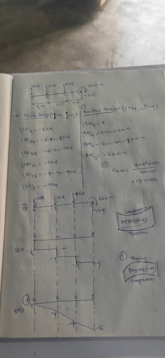
Problem#1 (10 points): For each beam in the figure below, determine the following: a) Shear forces...
S4. For the beam with loading shown in Figure 4.0, a. Draw the shear and bending-moment...
 S4. For the beam with loading shown in Figure 4.0, a. Draw the shear and bending-moment diagrams for the beamA b. Deternine the maximum normal stress due to bending and shearing stress of the beams 45 kN m 16 kN m 250 mm A 75 mm 2.4 m 1.2 m Figure 4.0
2. A cantilever beam is loaded as shown in the following figure. 1) Draw the shear...
 2. A cantilever beam is loaded as shown in the following figure. 1) Draw the shear force and bending moment diagrams 2) Calculate the maximum bending stress in the beam. S 3) Calculate themaximum transverse shear stress in the beam. 19 kN 3 kN/m NA 01 m 2 m 2 m 2 m
Q.3. [20 pts) The figure below shows the shear force diagram for a loaded beam. a-)...
 Q.3. [20 pts) The figure below shows the shear force diagram for a loaded beam. a-) Sketch the beam, showing the loading conditions. b-) Draw the bending moment diagram showing the critical values. V (kN) *** 1.6 2.4 36 16 20 -x (m) 1-24 40
A simply support beam is loaded as shown in the following figure. 1) Draw the shear...
 A simply support beam is loaded as shown in the following figure. 1) Draw the shear force and bending moment diagrams. 2) Calculate the maximum bending stress in the beam. 3) Calculate the maximum shear stress in the beam. G0 KN 30 kNm B0 kN/m H NA 0.1 m 3 m e 1.5m to 1.5m. 0.1 m
4kN 150 mm 2kN Problem 1, subjected to two concentrated forces and has a as shown in the figures The cantilever beam, (fixed at A)s 0 mm30 mm -30 mm (a) Determine the maximum shear stress on the...
 4kN 150 mm 2kN Problem 1, subjected to two concentrated forces and has a as shown in the figures The cantilever beam, (fixed at A)s 0 mm30 mm -30 mm (a) Determine the maximum shear stress on the section (b) Determine the maximum bending stress in compression and in tension (c) If the allowable bending stress (for tension and compression) is ơao.-6 MPa, calculate the new minimum required section modulus.
4kN 150 mm 2kN Problem 1, subjected to two concentrated...
4kN 150 mm 2kN Problem 1, subjected to two concentrated forces and has a as shown in the figures The cantilever beam, (fixed at A)s 0 mm30 mm -30 mm (a) Determine the maximum shear stress on the section (b) Determine the maximum bending stress in compression and in tension (c) If the allowable bending stress (for tension and compression) is ơao.-6 MPa, calculate the new minimum required section modulus.
4kN 150 mm 2kN Problem 1, subjected to two concentrated...
For the beam below solve a) Reaction forces 20% b) Shear force diagram in Matlab or...
 For the beam below solve a) Reaction forces 20% b) Shear force diagram in Matlab or excel 20% e) Write a bending moment equation for each section of the beam in terms of x d) Bending moment diagram in Matlab or 40% excel 20% 30 kN 20 kN/m 10 kN (m) 2 8
For the beam below solve a) Reaction forces 20% b) Shear force diagram in Matlab or excel 20% e) Write a bending moment equation for each section...
For the beam below solve a) Reaction forces 20% b) Shear force diagram in Matlab or excel 20% e) Write a bending moment equation for each section of the beam in terms of x d) Bending moment diagram in Matlab or 40% excel 20% 30 kN 20 kN/m 10 kN (m) 2 8
For the beam below solve a) Reaction forces 20% b) Shear force diagram in Matlab or excel 20% e) Write a bending moment equation for each section...
For the beam shown below (neglect self-weight of the beam) 16 kN x 8 mm 19...
 For the beam shown below (neglect self-weight of the beam) 16 kN x 8 mm 19 kN 10 kN/m T 2 mm mm A4n - 3 m +3m → a. Draw the shear force and bending moment diagram. 2 mm Section X-X b. For the cross section x-x given, calculate the maximum tensile and compressive bending stress c. For the cross section X-X given, calculate the maximum shear stress
For the beam and loading shown draw a shear and moment diagram then determine the minimum...
 For the beam and loading shown draw a shear and moment diagram
then determine the minimum required width b, knowing that for the
grade of timber used, the maximum allowable normal stress is 12 MPa
and the maximum allowable shear stress is 822 kPa. The dimensions
are the following: a = 148 mm, LAB = 0.9 m,
LBC = 1.1 m, LCE = 1.1 m, LED =
0.5 m, and the loading is PB = 2.3 kN, PC =
4.7...
For the beam and loading shown draw a shear and moment diagram
then determine the minimum required width b, knowing that for the
grade of timber used, the maximum allowable normal stress is 12 MPa
and the maximum allowable shear stress is 822 kPa. The dimensions
are the following: a = 148 mm, LAB = 0.9 m,
LBC = 1.1 m, LCE = 1.1 m, LED =
0.5 m, and the loading is PB = 2.3 kN, PC =
4.7...
1. For the overhanging beam in the figure below, determine the maximum shear stress, the maximum...
 1. For the overhanging beam in the figure below, determine the maximum shear stress, the maximum tensile stress, and the maximum compressive stress in the beam due to the loading shown. 300 lb/ft 6 in. 1 in. 4 ft 10 ft 1 in. 2 in. Section INSTRUCTIONS For PROBLEM do the following steps: 1. Show ALL your work 2. Draw appropriately labeled FBDs 3. Use appropriate segments to develop expressions for the shear force and bending moment. diagrams in a...
For the beam and loading shown (a) Determine the reactions at A. (b) Draw the shear...
 For the beam and loading shown (a) Determine the reactions at A. (b) Draw the shear and bending moment diagrams for the beam. 2 kN А c B 2 m 2 m 1 kN
 S4. For the beam with loading shown in Figure 4.0, a. Draw the shear and bending-moment diagrams for the beamA b. Deternine the maximum normal stress due to bending and shearing stress of the beams 45 kN m 16 kN m 250 mm A 75 mm 2.4 m 1.2 m Figure 4.0
 2. A cantilever beam is loaded as shown in the following figure. 1) Draw the shear force and bending moment diagrams 2) Calculate the maximum bending stress in the beam. S 3) Calculate themaximum transverse shear stress in the beam. 19 kN 3 kN/m NA 01 m 2 m 2 m 2 m
 Q.3. [20 pts) The figure below shows the shear force diagram for a loaded beam. a-) Sketch the beam, showing the loading conditions. b-) Draw the bending moment diagram showing the critical values. V (kN) *** 1.6 2.4 36 16 20 -x (m) 1-24 40
 A simply support beam is loaded as shown in the following figure. 1) Draw the shear force and bending moment diagrams. 2) Calculate the maximum bending stress in the beam. 3) Calculate the maximum shear stress in the beam. G0 KN 30 kNm B0 kN/m H NA 0.1 m 3 m e 1.5m to 1.5m. 0.1 m
 4kN 150 mm 2kN Problem 1, subjected to two concentrated forces and has a as shown in the figures The cantilever beam, (fixed at A)s 0 mm30 mm -30 mm (a) Determine the maximum shear stress on the section (b) Determine the maximum bending stress in compression and in tension (c) If the allowable bending stress (for tension and compression) is ơao.-6 MPa, calculate the new minimum required section modulus.
4kN 150 mm 2kN Problem 1, subjected to two concentrated...
4kN 150 mm 2kN Problem 1, subjected to two concentrated forces and has a as shown in the figures The cantilever beam, (fixed at A)s 0 mm30 mm -30 mm (a) Determine the maximum shear stress on the section (b) Determine the maximum bending stress in compression and in tension (c) If the allowable bending stress (for tension and compression) is ơao.-6 MPa, calculate the new minimum required section modulus.
4kN 150 mm 2kN Problem 1, subjected to two concentrated...
 For the beam below solve a) Reaction forces 20% b) Shear force diagram in Matlab or excel 20% e) Write a bending moment equation for each section of the beam in terms of x d) Bending moment diagram in Matlab or 40% excel 20% 30 kN 20 kN/m 10 kN (m) 2 8
For the beam below solve a) Reaction forces 20% b) Shear force diagram in Matlab or excel 20% e) Write a bending moment equation for each section...
For the beam below solve a) Reaction forces 20% b) Shear force diagram in Matlab or excel 20% e) Write a bending moment equation for each section of the beam in terms of x d) Bending moment diagram in Matlab or 40% excel 20% 30 kN 20 kN/m 10 kN (m) 2 8
For the beam below solve a) Reaction forces 20% b) Shear force diagram in Matlab or excel 20% e) Write a bending moment equation for each section...
 For the beam shown below (neglect self-weight of the beam) 16 kN x 8 mm 19 kN 10 kN/m T 2 mm mm A4n - 3 m +3m → a. Draw the shear force and bending moment diagram. 2 mm Section X-X b. For the cross section x-x given, calculate the maximum tensile and compressive bending stress c. For the cross section X-X given, calculate the maximum shear stress
 For the beam and loading shown draw a shear and moment diagram
then determine the minimum required width b, knowing that for the
grade of timber used, the maximum allowable normal stress is 12 MPa
and the maximum allowable shear stress is 822 kPa. The dimensions
are the following: a = 148 mm, LAB = 0.9 m,
LBC = 1.1 m, LCE = 1.1 m, LED =
0.5 m, and the loading is PB = 2.3 kN, PC =
4.7...
For the beam and loading shown draw a shear and moment diagram
then determine the minimum required width b, knowing that for the
grade of timber used, the maximum allowable normal stress is 12 MPa
and the maximum allowable shear stress is 822 kPa. The dimensions
are the following: a = 148 mm, LAB = 0.9 m,
LBC = 1.1 m, LCE = 1.1 m, LED =
0.5 m, and the loading is PB = 2.3 kN, PC =
4.7...
 1. For the overhanging beam in the figure below, determine the maximum shear stress, the maximum tensile stress, and the maximum compressive stress in the beam due to the loading shown. 300 lb/ft 6 in. 1 in. 4 ft 10 ft 1 in. 2 in. Section INSTRUCTIONS For PROBLEM do the following steps: 1. Show ALL your work 2. Draw appropriately labeled FBDs 3. Use appropriate segments to develop expressions for the shear force and bending moment. diagrams in a...
 For the beam and loading shown (a) Determine the reactions at A. (b) Draw the shear and bending moment diagrams for the beam. 2 kN А c B 2 m 2 m 1 kN
Most questions answered within 3 hours.
-
I create an address book where the user enters the name, phone
and email in the...
asked 3 minutes ago -
The production capacity for acrylonitrile
(C3H3N) in the United States exceeds 2
million pounds per year....
asked 10 minutes ago -
explain and comment out your answer
43. How many address lines are required to address a...
asked 17 minutes ago -
A sample of 45 observations is selected from a normal
population. The sample mean is 49,...
asked 31 minutes ago -
A construction company is planning to bid on a building
contract. The bid costs the company...
asked 29 minutes ago -
A firm operating in a purely competitive environment is faced
with a market price of $250....
asked 35 minutes ago -
•Let’s say someone claims the average population size is
600 feet squared and the housing authority...
asked 43 minutes ago -
Cynaide is a deadly poison that blocks the last step in the
electron transport chain of...
asked 47 minutes ago -
Your friend tells you that there is a vending machine on campus
that dispenses M&M packs...
asked 1 hour ago -
What advantages are there to using piperidine rather than
hydroxide as a base?
asked 1 hour ago -
7. The life of a Freeze Breeze electric fan is normally
distributed with a mean 4...
asked 1 hour ago -
1. A 751 mL NaCl solution is diluted to a volume of 1.06 L and a...
asked 1 hour ago