
Homework Answers


Add Answer to:
4kN 150 mm 2kN Problem 1, subjected to two concentrated forces and has a as shown in the figures The cantilever beam, (fixed at A)s 0 mm30 mm -30 mm (a) Determine the maximum shear stress on the...
4kN 150 mm 2kN Problem 1, subjected to two concentrated forces and has a as shown...
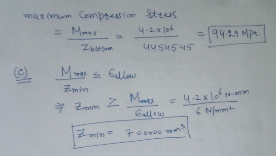
 4kN 150 mm 2kN Problem 1, subjected to two concentrated forces and has a as shown in the figures The cantilever beam, (fixed at A)s 0 mm30 mm -30 mm (a) Determine the maximum shear stress on the section (b) Determine the maximum bending stress in compression and in tension (c) If the allowable bending stress (for tension and compression) is ơao.-6 MPa, calculate the new minimum required section modulus.
The cantilever beam shown in the figure is subjected to a concentrated load at point B....
 The cantilever beam shown in the figure is subjected to a concentrated load at point B. The stresses acting at point Hon the beam are to be determined Ques! Text- Quest Text Ent T Quest Text End Cross section Viewir Text-Ent For this analysis, use the following values Beam and Load. Questi Muitstep a. 1.75 m b-0.30 m 0.63 degrees P.49 KN Questid Text Entry Questio Text Entry Cross-sectional Dimensions d - 275 mm by - 150 mm - 13...
The cantilever beam shown in the figure is subjected to a concentrated load at point B....
 The cantilever beam shown in the figure is subjected to a concentrated load at point B. The stresses acting at point H on the beam are to be determined. H Cross section For this analysis, use the following values: Beam and Load. a = 1.75 m b=0.30 m @= 60 degrees P = 25 KN Cross-sectional Dimensions d=250 mm bp = 125 mm ty=7 mm tw = 7 mm C= 30 mm (Note: The load P applied at Bacts in...
PROBLEM 3 Knowing that for the cantilever beam shown in Figure 3, the allowable stress is...
 PROBLEM 3
Knowing that for the cantilever beam shown in Figure 3, the
allowable stress is 120 MPa in tension and 150 MPa in compression,
determine the largest couple M that can be applied.
Figure 3 (b) Section a-a (dimension not to scale) "Х Figure 3(c) 610UB125 Figure 3(d) 300PFC dt(X10s yo section | x | y (x106 2 mm 986 72.4 610UB125 1600022961219.6 11.9 5110 90 300 16 39.3 4.04 300PFC 24.1 Figure 3 (a)Cantilever beam 300PFC 610UB125 Figure...
PROBLEM 3
Knowing that for the cantilever beam shown in Figure 3, the
allowable stress is 120 MPa in tension and 150 MPa in compression,
determine the largest couple M that can be applied.
Figure 3 (b) Section a-a (dimension not to scale) "Х Figure 3(c) 610UB125 Figure 3(d) 300PFC dt(X10s yo section | x | y (x106 2 mm 986 72.4 610UB125 1600022961219.6 11.9 5110 90 300 16 39.3 4.04 300PFC 24.1 Figure 3 (a)Cantilever beam 300PFC 610UB125 Figure...
The cantilever beam is subjected to the point loads P1=3kN and P2=6kN The cantilever beam is...
 The cantilever beam is subjected to the point loads
P1=3kN and P2=6kN
The cantilever beam is subjected to the point loads P 3 kN and P 6 kN 250 mm250mm-+ -300 mm 20m.m 70 mm 20 mm 50 mm Part A Determine the maximum shear stress acting at section a a of the cantilevered strut Express your answer to three significant figures and include appropriate units. x2.65 MPa max Submit Previous Answers Request Answer
The cantilever beam is subjected to the point loads
P1=3kN and P2=6kN
The cantilever beam is subjected to the point loads P 3 kN and P 6 kN 250 mm250mm-+ -300 mm 20m.m 70 mm 20 mm 50 mm Part A Determine the maximum shear stress acting at section a a of the cantilevered strut Express your answer to three significant figures and include appropriate units. x2.65 MPa max Submit Previous Answers Request Answer
3- Determine the maximum shear stress in the beam section shown in the figure. Determine also...
 3- Determine the maximum shear stress in the beam section shown in the figure. Determine also the rate of twist of the beam section if the shear modulus G is 25 GPa. 100 mm T-25 N.m 3 mm 3 mm 50 mm 80 mm 2 mm
3- Determine the maximum shear stress in the beam section shown in the figure. Determine also the rate of twist of the beam section if the shear modulus G is 25 GPa. 100 mm...
3- Determine the maximum shear stress in the beam section shown in the figure. Determine also the rate of twist of the beam section if the shear modulus G is 25 GPa. 100 mm T-25 N.m 3 mm 3 mm 50 mm 80 mm 2 mm
3- Determine the maximum shear stress in the beam section shown in the figure. Determine also the rate of twist of the beam section if the shear modulus G is 25 GPa. 100 mm...
Calculate the maximum bending and shear stress for the cantilever beam with the cross section shown...
 Calculate the maximum bending and shear stress for the cantilever
beam with the cross section shown
30 kip 4 ft 1 in. 8 in. I 10 in. 0.6 in.-
Calculate the maximum bending and shear stress for the cantilever
beam with the cross section shown
30 kip 4 ft 1 in. 8 in. I 10 in. 0.6 in.-
A 5-m-long simply supported timber beam carries two concentrated loads as shown dimensions of the beam...
 A 5-m-long simply supported timber beam carries two concentrated loads as shown dimensions of the beam are shown a) At section a-a e the magnitude of the shear stress in the beam at point H. -7748 KNIm in the beam at point K the beam, at any location within the 5-m span length. V occurs in the beam at any location within the 5-m span length.)diagr. the magnitude of the shear stress (b) At section a-a, (e) Determine the maximum...
The built-up beam is made of steel as shown in Figure 1. Knowing that modulus of...
 The built-up beam is made of steel as shown in Figure 1. Knowing that modulus of elasticity for the steel is E = 200 GPa 150 mm 20 mm 150 mm 150 mm 10 mm M '10 mm 300 mm А Figure 1 (1) If the allowable tensile and compressive stress for the beam are allow tension = 140 MPa and o = 210 MPa. allow compression respectively, determine the maximum allowable internal moment M that can be applied Determine...
This problem consists of six questions. The aluminum (E = 10,000,000 psi) cantilever beam shown below...
 This problem consists of six questions. The aluminum (E = 10,000,000 psi) cantilever beam shown below is fixed at A and free at D. The beam subjected to a concentrated moment at D and a point load at C. 1.5" 100 lb 1500 lb-in 3.5" 30 in 42 in 50 in 22 in 0.5" 72 in Cross-section 1-5.36 in In the questions below, maximum means maximum in magnitude. Include the negative sign to indicated compression. Question 1 10 pts Determine...
 4kN 150 mm 2kN Problem 1, subjected to two concentrated forces and has a as shown in the figures The cantilever beam, (fixed at A)s 0 mm30 mm -30 mm (a) Determine the maximum shear stress on the section (b) Determine the maximum bending stress in compression and in tension (c) If the allowable bending stress (for tension and compression) is ơao.-6 MPa, calculate the new minimum required section modulus.
 The cantilever beam shown in the figure is subjected to a concentrated load at point B. The stresses acting at point Hon the beam are to be determined Ques! Text- Quest Text Ent T Quest Text End Cross section Viewir Text-Ent For this analysis, use the following values Beam and Load. Questi Muitstep a. 1.75 m b-0.30 m 0.63 degrees P.49 KN Questid Text Entry Questio Text Entry Cross-sectional Dimensions d - 275 mm by - 150 mm - 13...
 The cantilever beam shown in the figure is subjected to a concentrated load at point B. The stresses acting at point H on the beam are to be determined. H Cross section For this analysis, use the following values: Beam and Load. a = 1.75 m b=0.30 m @= 60 degrees P = 25 KN Cross-sectional Dimensions d=250 mm bp = 125 mm ty=7 mm tw = 7 mm C= 30 mm (Note: The load P applied at Bacts in...
 PROBLEM 3
Knowing that for the cantilever beam shown in Figure 3, the
allowable stress is 120 MPa in tension and 150 MPa in compression,
determine the largest couple M that can be applied.
Figure 3 (b) Section a-a (dimension not to scale) "Х Figure 3(c) 610UB125 Figure 3(d) 300PFC dt(X10s yo section | x | y (x106 2 mm 986 72.4 610UB125 1600022961219.6 11.9 5110 90 300 16 39.3 4.04 300PFC 24.1 Figure 3 (a)Cantilever beam 300PFC 610UB125 Figure...
PROBLEM 3
Knowing that for the cantilever beam shown in Figure 3, the
allowable stress is 120 MPa in tension and 150 MPa in compression,
determine the largest couple M that can be applied.
Figure 3 (b) Section a-a (dimension not to scale) "Х Figure 3(c) 610UB125 Figure 3(d) 300PFC dt(X10s yo section | x | y (x106 2 mm 986 72.4 610UB125 1600022961219.6 11.9 5110 90 300 16 39.3 4.04 300PFC 24.1 Figure 3 (a)Cantilever beam 300PFC 610UB125 Figure...
 The cantilever beam is subjected to the point loads
P1=3kN and P2=6kN
The cantilever beam is subjected to the point loads P 3 kN and P 6 kN 250 mm250mm-+ -300 mm 20m.m 70 mm 20 mm 50 mm Part A Determine the maximum shear stress acting at section a a of the cantilevered strut Express your answer to three significant figures and include appropriate units. x2.65 MPa max Submit Previous Answers Request Answer
The cantilever beam is subjected to the point loads
P1=3kN and P2=6kN
The cantilever beam is subjected to the point loads P 3 kN and P 6 kN 250 mm250mm-+ -300 mm 20m.m 70 mm 20 mm 50 mm Part A Determine the maximum shear stress acting at section a a of the cantilevered strut Express your answer to three significant figures and include appropriate units. x2.65 MPa max Submit Previous Answers Request Answer
 3- Determine the maximum shear stress in the beam section shown in the figure. Determine also the rate of twist of the beam section if the shear modulus G is 25 GPa. 100 mm T-25 N.m 3 mm 3 mm 50 mm 80 mm 2 mm
3- Determine the maximum shear stress in the beam section shown in the figure. Determine also the rate of twist of the beam section if the shear modulus G is 25 GPa. 100 mm...
3- Determine the maximum shear stress in the beam section shown in the figure. Determine also the rate of twist of the beam section if the shear modulus G is 25 GPa. 100 mm T-25 N.m 3 mm 3 mm 50 mm 80 mm 2 mm
3- Determine the maximum shear stress in the beam section shown in the figure. Determine also the rate of twist of the beam section if the shear modulus G is 25 GPa. 100 mm...
 Calculate the maximum bending and shear stress for the cantilever
beam with the cross section shown
30 kip 4 ft 1 in. 8 in. I 10 in. 0.6 in.-
Calculate the maximum bending and shear stress for the cantilever
beam with the cross section shown
30 kip 4 ft 1 in. 8 in. I 10 in. 0.6 in.-
 A 5-m-long simply supported timber beam carries two concentrated loads as shown dimensions of the beam are shown a) At section a-a e the magnitude of the shear stress in the beam at point H. -7748 KNIm in the beam at point K the beam, at any location within the 5-m span length. V occurs in the beam at any location within the 5-m span length.)diagr. the magnitude of the shear stress (b) At section a-a, (e) Determine the maximum...
 The built-up beam is made of steel as shown in Figure 1. Knowing that modulus of elasticity for the steel is E = 200 GPa 150 mm 20 mm 150 mm 150 mm 10 mm M '10 mm 300 mm А Figure 1 (1) If the allowable tensile and compressive stress for the beam are allow tension = 140 MPa and o = 210 MPa. allow compression respectively, determine the maximum allowable internal moment M that can be applied Determine...
 This problem consists of six questions. The aluminum (E = 10,000,000 psi) cantilever beam shown below is fixed at A and free at D. The beam subjected to a concentrated moment at D and a point load at C. 1.5" 100 lb 1500 lb-in 3.5" 30 in 42 in 50 in 22 in 0.5" 72 in Cross-section 1-5.36 in In the questions below, maximum means maximum in magnitude. Include the negative sign to indicated compression. Question 1 10 pts Determine...
Most questions answered within 3 hours.
-
The vapor pressure of a solution containing 38.7 g glycerin
(C3H8O3) in 146.2 g ethanol (C2H5OH)...
asked 2 minutes ago -
without using map
1. Write a C++ program to find out the top 10 words in...
asked 4 minutes ago -
A physics major is cooking breakfast when he notices that the
frictional force between the steel...
asked 7 minutes ago -
1)Calculate the percent ionization of a
0.330 M solution of hypochlorous
acid.
% Ionization = %...
asked 6 minutes ago -
A cyclohexane (c-hex) solution is prepared by fully dissolving
9.11g of a newly synthesized organic compound...
asked 13 minutes ago -
SCHEME :-)
[5 marks] Write a procedure called convert that takes as
arguments: a temperature value...
asked 20 minutes ago -
Are
Acetyl CoA and Pyruvate biological molecules that are used to get
ATP energy in aerobic...
asked 21 minutes ago -
Two waves are traveling on a string, one with a wave function,
y1 = 0.05sin(4x -...
asked 28 minutes ago -
Develop an ideal customer profile for three Dell Customer
groups( a supplier, a global business, and...
asked 31 minutes ago -
Suppose, for any future year, the probability its October rain
is more than 3 inches is...
asked 35 minutes ago -
Solve the following systems of linear equations using
substitution 12p + 3q = 15 6q +...
asked 42 minutes ago -
Prof. D went grocery shopping and purchased one dozen eggs and
one pound of flour (all...
asked 49 minutes ago