
Homework Answers
Add Answer to:
This problem consists of six questions. The aluminum (E = 10,000,000 psi) cantilever beam shown below...
a. Draw a free-body diagram for the beam shown above and derive expressions for the support...
 a. Draw a free-body diagram for the beam shown above and derive
expressions for the support reactions at A and B
b. Draw internal force (shear and bending moment) diagrams.
c. If a = 10 ft and M0 = 200 ft-lb, use the dimensions of the
beam cross-section, provided on the previous page, to compute the
maximum flexural and shear stresses on the beam cross-section.
d. If the allowable bending stress is 925 psi and the allowable
shear stress is...
a. Draw a free-body diagram for the beam shown above and derive
expressions for the support reactions at A and B
b. Draw internal force (shear and bending moment) diagrams.
c. If a = 10 ft and M0 = 200 ft-lb, use the dimensions of the
beam cross-section, provided on the previous page, to compute the
maximum flexural and shear stresses on the beam cross-section.
d. If the allowable bending stress is 925 psi and the allowable
shear stress is...
4. A cantilever beam is loaded as shown in the figure. Using the method of sections...
 4. A cantilever beam is loaded as shown in the figure. Using the method of sections or the integration method, draw the shear force diagram and the bending moment diagram. If the beam cross-section is a 9 inch square, find the maximum bending stress 1200 lb 800 lb/ft 9" B 9" A Beam cross-section 8 ft 8 ft
Q3 (25 pts) 3. For the cantilever beam shown below and to the left, Determine the...
 Q3
(25 pts) 3. For the cantilever beam shown below and to the left, Determine the reactions at the wall at C. Draw the shear (V) and moment (M) diagram for the beam and label the appropriate values. For the given cross section, determine the magnitude of the maximum COMPRESSIVE bending stress and state where this occurs along the length of the beam and along the height of the beam (top or bottom). Sketch the NORMAL stress distribution (profile) for...
Q3
(25 pts) 3. For the cantilever beam shown below and to the left, Determine the reactions at the wall at C. Draw the shear (V) and moment (M) diagram for the beam and label the appropriate values. For the given cross section, determine the magnitude of the maximum COMPRESSIVE bending stress and state where this occurs along the length of the beam and along the height of the beam (top or bottom). Sketch the NORMAL stress distribution (profile) for...
1. (28 pts) A cantilever beam is subjected to the loads as shown in the figure....
 1. (28 pts) A cantilever beam is subjected to the loads as shown in the figure. Va) Draw a free-body diagram and determine the supports at point 0. b) Draw shear and moment diagrams and find the values at key points (i.e. x = 0, 6 and 10 ft). If possible, please show your calculations. c) Find shear force V(x) and bending moment M(x) for () <x<6 ft. 12 10 kip 2 kip/ft skip سے 40 kip.lt 611 4 11...
Question 3: A steel (E 30x106 psi and v 0.3) cantilever l-beam is subjected to a...
 Question 3: A steel (E 30x106 psi and v 0.3) cantilever l-beam is subjected to a distributed load and a concentrated load. The I section is 4-inch-wide and 5-inch-tall, and the flange and web plates are all 0.5-inch-thick, as marked in the figure. a) Draw the moment diagram as a function of x and clearly label the moment values at 1, 2, and 4 ft. (10) b) Find the maximum tensile (normal) stress in the entire beam. (5) c) Find...
A cantilever beam supports the loads shown. The cross-sectional dimensions of the shape are also shown....
 A cantilever beam supports the
loads shown. The cross-sectional dimensions of the shape are also
shown. Assume LAB = 4.0 ft,
LBC = 12.0 ft, w = 1620 lb/ft,
P = 2550 lb, b = 16 in., d = 6 in.,
t = 0.50 in. Determine
(a) the maximum horizontal shear stress.
(b) the maximum compression bending stress.
(c) the maximum tension bending stress.
Chapter 9, Supplemental Question 043 (GO Tutorial) A cantilever beam supports the loads shown. The cross...
A cantilever beam supports the
loads shown. The cross-sectional dimensions of the shape are also
shown. Assume LAB = 4.0 ft,
LBC = 12.0 ft, w = 1620 lb/ft,
P = 2550 lb, b = 16 in., d = 6 in.,
t = 0.50 in. Determine
(a) the maximum horizontal shear stress.
(b) the maximum compression bending stress.
(c) the maximum tension bending stress.
Chapter 9, Supplemental Question 043 (GO Tutorial) A cantilever beam supports the loads shown. The cross...
System Description The system consists of a beam with (see figure 1) Two simple supports A...
 System Description The system consists of a beam with (see figure 1) Two simple supports A distributed load and a concentrated load An inverted "U" shaped cross section (see figure 2); moment of inertia 9 in 200 lbf/in、 650 Ibf 10° 30 21" 40 Figure 1-system to be analyzed L4.5 1.72.25" NA 5.75 3.5 1.75" 1.5 Figure 2-cross section to be used Questions-Given that the applied loads and dimensions do the following 25 points 1. Determine and draw a shear...
2. A cantilever beam is loaded as shown in the following figure. 1) Draw the shear...
 2. A cantilever beam is loaded as shown in the following figure. 1) Draw the shear force and bending moment diagrams 2) Calculate the maximum bending stress in the beam. S 3) Calculate themaximum transverse shear stress in the beam. 19 kN 3 kN/m NA 01 m 2 m 2 m 2 m
The cantilever beam shown is subjected to a concentrated load of P = 34500 lb. The...
 The cantilever beam shown is subjected to a concentrated load of P = 34500 lb. The cross-sectional dimensions and the moment of inertia of the W16x31 wide-flange shape are: d = 15.9 in. tw = 0.275 in. be= 5.53 in. tp = 0.440 in. 12 = 375 in 4 Compute the value of the shear stress at point K, located at yk = 2.4 in. above the centroidal axis. bi 11 y 1 K Ук | Ун H Answer: Shear...
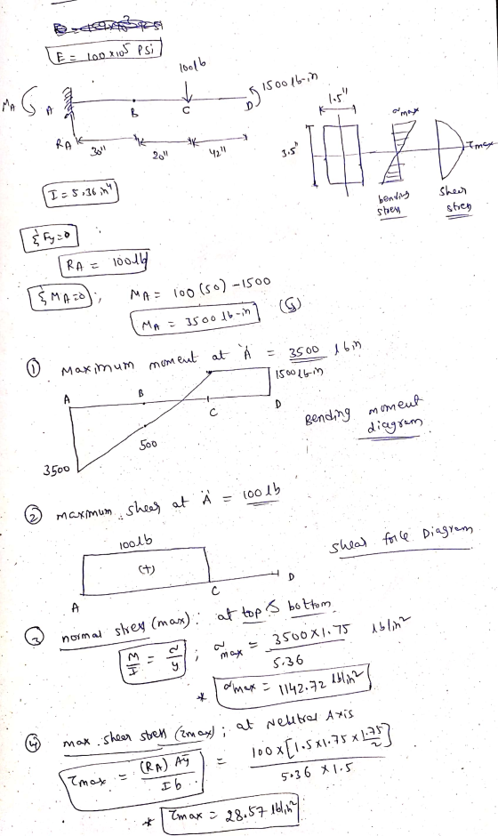
The cantilever beam shown is subjected to a moment at A and a distributed load that...
 The cantilever beam shown is subjected to a moment at A
and a distributed load that acts over segment BC, and is
fixed at C. Determine the reactions at the support located
at C. Then write expressions for shear and bending moment
as a function of their positions along the beam. Finally, use these
expressions to construct shear and bending moment diagrams
Draw a free-body diagram of the beam on paper. Use your
free-body diagram to determine the reactions at...
The cantilever beam shown is subjected to a moment at A
and a distributed load that acts over segment BC, and is
fixed at C. Determine the reactions at the support located
at C. Then write expressions for shear and bending moment
as a function of their positions along the beam. Finally, use these
expressions to construct shear and bending moment diagrams
Draw a free-body diagram of the beam on paper. Use your
free-body diagram to determine the reactions at...
 a. Draw a free-body diagram for the beam shown above and derive
expressions for the support reactions at A and B
b. Draw internal force (shear and bending moment) diagrams.
c. If a = 10 ft and M0 = 200 ft-lb, use the dimensions of the
beam cross-section, provided on the previous page, to compute the
maximum flexural and shear stresses on the beam cross-section.
d. If the allowable bending stress is 925 psi and the allowable
shear stress is...
a. Draw a free-body diagram for the beam shown above and derive
expressions for the support reactions at A and B
b. Draw internal force (shear and bending moment) diagrams.
c. If a = 10 ft and M0 = 200 ft-lb, use the dimensions of the
beam cross-section, provided on the previous page, to compute the
maximum flexural and shear stresses on the beam cross-section.
d. If the allowable bending stress is 925 psi and the allowable
shear stress is...
 4. A cantilever beam is loaded as shown in the figure. Using the method of sections or the integration method, draw the shear force diagram and the bending moment diagram. If the beam cross-section is a 9 inch square, find the maximum bending stress 1200 lb 800 lb/ft 9" B 9" A Beam cross-section 8 ft 8 ft
 Q3
(25 pts) 3. For the cantilever beam shown below and to the left, Determine the reactions at the wall at C. Draw the shear (V) and moment (M) diagram for the beam and label the appropriate values. For the given cross section, determine the magnitude of the maximum COMPRESSIVE bending stress and state where this occurs along the length of the beam and along the height of the beam (top or bottom). Sketch the NORMAL stress distribution (profile) for...
Q3
(25 pts) 3. For the cantilever beam shown below and to the left, Determine the reactions at the wall at C. Draw the shear (V) and moment (M) diagram for the beam and label the appropriate values. For the given cross section, determine the magnitude of the maximum COMPRESSIVE bending stress and state where this occurs along the length of the beam and along the height of the beam (top or bottom). Sketch the NORMAL stress distribution (profile) for...
 1. (28 pts) A cantilever beam is subjected to the loads as shown in the figure. Va) Draw a free-body diagram and determine the supports at point 0. b) Draw shear and moment diagrams and find the values at key points (i.e. x = 0, 6 and 10 ft). If possible, please show your calculations. c) Find shear force V(x) and bending moment M(x) for () <x<6 ft. 12 10 kip 2 kip/ft skip سے 40 kip.lt 611 4 11...
 Question 3: A steel (E 30x106 psi and v 0.3) cantilever l-beam is subjected to a distributed load and a concentrated load. The I section is 4-inch-wide and 5-inch-tall, and the flange and web plates are all 0.5-inch-thick, as marked in the figure. a) Draw the moment diagram as a function of x and clearly label the moment values at 1, 2, and 4 ft. (10) b) Find the maximum tensile (normal) stress in the entire beam. (5) c) Find...
 A cantilever beam supports the
loads shown. The cross-sectional dimensions of the shape are also
shown. Assume LAB = 4.0 ft,
LBC = 12.0 ft, w = 1620 lb/ft,
P = 2550 lb, b = 16 in., d = 6 in.,
t = 0.50 in. Determine
(a) the maximum horizontal shear stress.
(b) the maximum compression bending stress.
(c) the maximum tension bending stress.
Chapter 9, Supplemental Question 043 (GO Tutorial) A cantilever beam supports the loads shown. The cross...
A cantilever beam supports the
loads shown. The cross-sectional dimensions of the shape are also
shown. Assume LAB = 4.0 ft,
LBC = 12.0 ft, w = 1620 lb/ft,
P = 2550 lb, b = 16 in., d = 6 in.,
t = 0.50 in. Determine
(a) the maximum horizontal shear stress.
(b) the maximum compression bending stress.
(c) the maximum tension bending stress.
Chapter 9, Supplemental Question 043 (GO Tutorial) A cantilever beam supports the loads shown. The cross...
 System Description The system consists of a beam with (see figure 1) Two simple supports A distributed load and a concentrated load An inverted "U" shaped cross section (see figure 2); moment of inertia 9 in 200 lbf/in、 650 Ibf 10° 30 21" 40 Figure 1-system to be analyzed L4.5 1.72.25" NA 5.75 3.5 1.75" 1.5 Figure 2-cross section to be used Questions-Given that the applied loads and dimensions do the following 25 points 1. Determine and draw a shear...
 2. A cantilever beam is loaded as shown in the following figure. 1) Draw the shear force and bending moment diagrams 2) Calculate the maximum bending stress in the beam. S 3) Calculate themaximum transverse shear stress in the beam. 19 kN 3 kN/m NA 01 m 2 m 2 m 2 m
 The cantilever beam shown is subjected to a concentrated load of P = 34500 lb. The cross-sectional dimensions and the moment of inertia of the W16x31 wide-flange shape are: d = 15.9 in. tw = 0.275 in. be= 5.53 in. tp = 0.440 in. 12 = 375 in 4 Compute the value of the shear stress at point K, located at yk = 2.4 in. above the centroidal axis. bi 11 y 1 K Ук | Ун H Answer: Shear...
 The cantilever beam shown is subjected to a moment at A
and a distributed load that acts over segment BC, and is
fixed at C. Determine the reactions at the support located
at C. Then write expressions for shear and bending moment
as a function of their positions along the beam. Finally, use these
expressions to construct shear and bending moment diagrams
Draw a free-body diagram of the beam on paper. Use your
free-body diagram to determine the reactions at...
The cantilever beam shown is subjected to a moment at A
and a distributed load that acts over segment BC, and is
fixed at C. Determine the reactions at the support located
at C. Then write expressions for shear and bending moment
as a function of their positions along the beam. Finally, use these
expressions to construct shear and bending moment diagrams
Draw a free-body diagram of the beam on paper. Use your
free-body diagram to determine the reactions at...
Most questions answered within 3 hours.
-
Part 1- Inventory: You own a toy company and
you are producing wooden rocking horses. Assume...
asked 6 minutes ago -
What is aromaticity?
Identify aromatic molecules, especially those containing O, N,
S and B
asked 9 minutes ago -
A rubber solid circular wheel of uniform density spins about it
axis at rate of 60...
asked 21 minutes ago -
DNA evidence from an early human skeleton in Britain, shows that
early inhabitants of were blue...
asked 12 minutes ago -
Financial data for Joel de Paris, Inc., for last year
follow:
Joel de Paris, Inc.
Balance...
asked 20 minutes ago -
To practice Problem-Solving Strategy 19.1 Work in Ideal-gas
Processes.
A cylinder with initial volume V contains...
asked 29 minutes ago -
Depreciation for Partial Periods Bean Delivery Company purchased
a new delivery truck for $35,400 on April...
asked 33 minutes ago -
Q 5.23:
Jonathan has been doing calculations to determine a missing
component. So far he has...
asked 31 minutes ago -
Use indifference curve and the daily income-leisure choice model
to explain graphically the behavior of employees...
asked 51 minutes ago -
Record the following transactions of Fashion Park in a
general journal. Fashion Park must charge 8...
asked 52 minutes ago -
Chapter 08 Python Assignment: Question 1-5
Please I need help in my python course.
Question 1...
asked 56 minutes ago -
1.
In a study of the effectiveness of
a new pain killer,
4646
out of
821821...
asked 1 hour ago