
Homework Answers


Add Answer to:
For
the circle given below, find the stres values on points A and B. On
a...
For the circle given below, find the stres values on points A and B. On a...
 For the circle given below, find the stres values on points A and B. On a diagram, show the distrubition of stress on the section. 20 KN 060 A 80
For the circle given below, find the stres values on points A and B. On a...
 For the circle given below, find the stres values on points A
and B. On a diagram, show the distrubition of stress on the
section.
20 kN ф60 A B 80
For the circle given below, find the stres values on points A
and B. On a diagram, show the distrubition of stress on the
section.
20 kN ф60 A B 80
(40 points) For the shown cantilever a. Find the reactions. (5 points) b. Draw the shear...
 (40 points) For the shown cantilever a. Find the reactions. (5 points) b. Draw the shear diagram. (5 points) c. Draw the moment diagram.(10 2 KN 250 mm-.--300 mm 4 KN 250 mm points) Determine the maximum tensile and compressive bending stresses (10 points) 20 mm d. 70 mm e. Determine the shear stress at point B 20 mm 50 mm on the web of the cantilevered strut at section a-a. (10 points)
PROBLEM 2: 40% A 6 kN force is exerted on the frame which has the T cross sectio analyze the states of stress at a section taken at 800 mm from the point of n shown below. It is required to 1. Fo...
 PROBLEM 2: 40% A 6 kN force is exerted on the frame which has the T cross sectio analyze the states of stress at a section taken at 800 mm from the point of n shown below. It is required to 1. For the given T cross section, find the centroid and the area moment of inertia I,. 2. Draw the free body diagram of the free end of the frame and determine the interna loadings at the centroid of...
For the joint and loading shown, determine the stress states at points A and B on...
 For the joint and loading shown, determine the stress states at
points A and B on section-aa, and the principle stresses at point
A. The free-body diagram including section-aa is given below for
your convenience. Section-aa has a rectangular cross-section area
of thickness 12 mm (shown) and width 18 mm. a) Sketch each stress
state using a square stress element. b) Determine the principle
stresses at point A (no need to sketch the stress
element).
Problem 1: (25%) For the...
For the joint and loading shown, determine the stress states at
points A and B on section-aa, and the principle stresses at point
A. The free-body diagram including section-aa is given below for
your convenience. Section-aa has a rectangular cross-section area
of thickness 12 mm (shown) and width 18 mm. a) Sketch each stress
state using a square stress element. b) Determine the principle
stresses at point A (no need to sketch the stress
element).
Problem 1: (25%) For the...
Find the state of stress at points A, B, and Clocated at the fixed support 1000 40 40 20 100 KN 1...
 Find the state of stress at points A, B, and Clocated at the fixed support 1000 40 40 20 100 KN 1000 20 300 kN 80 200 kN 40 40 A 20 Ce
Find the state of stress at points A, B, and Clocated at the fixed support 1000 40 40 20 100 KN 1000 20 300 kN 80 200 kN 40 40 A 20 Ce
Find the state of stress at points A, B, and Clocated at the fixed support 1000 40 40 20 100 KN 1000 20 300 kN 80 200 kN 40 40 A 20 Ce
LIU Points A hollow steel tube is bend to quarter circle and welded at base as...
 LIU Points A hollow steel tube is bend to quarter circle and welded at base as shown in the figure below. The radius of curvature at the center of cross section area is 400 mm. It is subjected to force F. Use the given data to find 1. The reaction forces and moments at the critical cross section area 2. Find the Von Mises stress at the critical location (Neglect transverse shear) 3. If the yield stress of the materials...
For the 1.5" shaft shown below: 10 in 2 B 1 200 lbf 10 in 1000 lbf 500 lbf 100 lbf 1. Draw the FB...
 For the 1.5" shaft shown below: 10 in 2 B 1 200 lbf 10 in 1000 lbf 500 lbf 100 lbf 1. Draw the FBD with all corresponding forces (10 points) 2. Draw the shear diagram with all corresponding values (20 points) 3. Draw the moment diagram with all corresponding values (20 points) 4. Find the location with the highest stress, what is the stress at this location? (20 points) 5. Use Mohr's circle or von Misses criteria to find...
For the beam shown below, find the maximum bending stress and maximum transverse shear stress. That...
 For the beam shown below, find the maximum bending stress and maximum transverse shear stress. That is, carry out load and stress analyses in the following order. Load Analysis Draw the load diagram or free body diagram (FBD) and determine the support reactions. Show your calculations. • Draw the shear force diagram (SFD). Show your calculations. Draw the bending moment diagram (BMD). Show your calculations. Stress Analysis Identify the critical section(s) and determine the maximum normal (bending) stress at the...
Given the stress element below: 1. Draw Mohr Circle for the stress element shown below. Use...
 Given the stress element below: 1. Draw Mohr Circle for the stress element shown below. Use proper scale and draw neatly. 2. Show and label the principal and max shear stress on the circle. 3. On the Mohr circle indicate the angles form the X-axis of Mohr circle to the o axis and Tmax axis. 4. Draw stress elements for initial, principal, maximum shear in their proper orientation. Mark all points on Mohr Circle and corresponding points on stress elements...
 For the circle given below, find the stres values on points A and B. On a diagram, show the distrubition of stress on the section. 20 KN 060 A 80
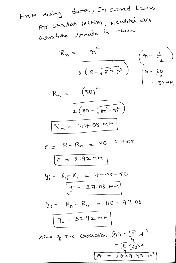
 For the circle given below, find the stres values on points A
and B. On a diagram, show the distrubition of stress on the
section.
20 kN ф60 A B 80
For the circle given below, find the stres values on points A
and B. On a diagram, show the distrubition of stress on the
section.
20 kN ф60 A B 80
 (40 points) For the shown cantilever a. Find the reactions. (5 points) b. Draw the shear diagram. (5 points) c. Draw the moment diagram.(10 2 KN 250 mm-.--300 mm 4 KN 250 mm points) Determine the maximum tensile and compressive bending stresses (10 points) 20 mm d. 70 mm e. Determine the shear stress at point B 20 mm 50 mm on the web of the cantilevered strut at section a-a. (10 points)
 PROBLEM 2: 40% A 6 kN force is exerted on the frame which has the T cross sectio analyze the states of stress at a section taken at 800 mm from the point of n shown below. It is required to 1. For the given T cross section, find the centroid and the area moment of inertia I,. 2. Draw the free body diagram of the free end of the frame and determine the interna loadings at the centroid of...
 For the joint and loading shown, determine the stress states at
points A and B on section-aa, and the principle stresses at point
A. The free-body diagram including section-aa is given below for
your convenience. Section-aa has a rectangular cross-section area
of thickness 12 mm (shown) and width 18 mm. a) Sketch each stress
state using a square stress element. b) Determine the principle
stresses at point A (no need to sketch the stress
element).
Problem 1: (25%) For the...
For the joint and loading shown, determine the stress states at
points A and B on section-aa, and the principle stresses at point
A. The free-body diagram including section-aa is given below for
your convenience. Section-aa has a rectangular cross-section area
of thickness 12 mm (shown) and width 18 mm. a) Sketch each stress
state using a square stress element. b) Determine the principle
stresses at point A (no need to sketch the stress
element).
Problem 1: (25%) For the...
 Find the state of stress at points A, B, and Clocated at the fixed support 1000 40 40 20 100 KN 1000 20 300 kN 80 200 kN 40 40 A 20 Ce
Find the state of stress at points A, B, and Clocated at the fixed support 1000 40 40 20 100 KN 1000 20 300 kN 80 200 kN 40 40 A 20 Ce
Find the state of stress at points A, B, and Clocated at the fixed support 1000 40 40 20 100 KN 1000 20 300 kN 80 200 kN 40 40 A 20 Ce
 LIU Points A hollow steel tube is bend to quarter circle and welded at base as shown in the figure below. The radius of curvature at the center of cross section area is 400 mm. It is subjected to force F. Use the given data to find 1. The reaction forces and moments at the critical cross section area 2. Find the Von Mises stress at the critical location (Neglect transverse shear) 3. If the yield stress of the materials...
 For the 1.5" shaft shown below: 10 in 2 B 1 200 lbf 10 in 1000 lbf 500 lbf 100 lbf 1. Draw the FBD with all corresponding forces (10 points) 2. Draw the shear diagram with all corresponding values (20 points) 3. Draw the moment diagram with all corresponding values (20 points) 4. Find the location with the highest stress, what is the stress at this location? (20 points) 5. Use Mohr's circle or von Misses criteria to find...
 For the beam shown below, find the maximum bending stress and maximum transverse shear stress. That is, carry out load and stress analyses in the following order. Load Analysis Draw the load diagram or free body diagram (FBD) and determine the support reactions. Show your calculations. • Draw the shear force diagram (SFD). Show your calculations. Draw the bending moment diagram (BMD). Show your calculations. Stress Analysis Identify the critical section(s) and determine the maximum normal (bending) stress at the...
 Given the stress element below: 1. Draw Mohr Circle for the stress element shown below. Use proper scale and draw neatly. 2. Show and label the principal and max shear stress on the circle. 3. On the Mohr circle indicate the angles form the X-axis of Mohr circle to the o axis and Tmax axis. 4. Draw stress elements for initial, principal, maximum shear in their proper orientation. Mark all points on Mohr Circle and corresponding points on stress elements...
Most questions answered within 3 hours.
-
) Raw materials are studied for contamination. Suppose that
the number of particles of contamination per...
asked 12 minutes ago -
After running a regression analysis we calculated an F test and
the significance level was 0.15....
asked 8 minutes ago -
----Can someone please help me solve this one using JAVA
----I thank you in advance
Create...
asked 13 minutes ago -
1. What force primarily attracts the potassium ion to
the nitrate ion?
a. London forces...
asked 15 minutes ago -
What are the negative effects of abruptly stopping the use of
all fossil fuels? Give at...
asked 21 minutes ago -
Given that many conflict are the result of different parties having
different interests, is it possible...
asked 26 minutes ago -
A 750 g block can slide uniformly along the horizontal track
when a string attached to...
asked 29 minutes ago -
In 2017, Juan entered into a contract to write a book. The
publisher advanced Juan $50,000,...
asked 43 minutes ago -
Determine the number of kinds of protons in each molecule (w/
respect to NMR spectroscopy). Drawing...
asked 53 minutes ago -
A jeweler whose near point is 68 cm from his eye uses a
magnifying glass as...
asked 51 minutes ago -
A company wants to determine how many units of each of two
products, A and B,...
asked 55 minutes ago -
The blood pressure of a person changes throughout the day.
Suppose the systolic blood pressure of...
asked 1 hour ago