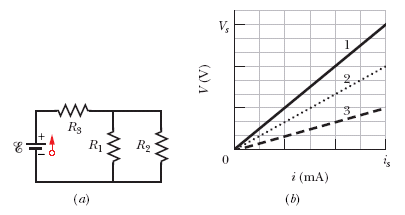
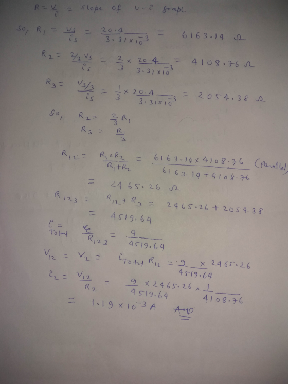
The ideal battery in Figure (a) has emf = 9.0 V. Plot 1 in Figure (b) gives the electric potential difference V that can appear across resistor 1 of the circuit versus the current i in that resistor. The scale of the V axis is set by Vs = 20.4 V, and the scale of the i axis is set by is = 3.31 mA. Plots 2 and 3 are similar plots for resistors 2 and 3, respectively. What is the current in resistor 2?
Homework Answers
Add Answer to:
The ideal battery in Figure (a) has emf =
9.0 V. Plot 1 in Figure (b) gives...
The ideal battery in Figure (a) has emf = 8.1 V. Plot 1 in Figure (b)...
The ideal battery in Figure (a) has emf = 8.1 V. Plot 1 in Figure (b) gives the electric potential difference V that can appear across resistor 1 of the circuit versus the current i in that resistor. The scale of the V axis is set by Vs = 19.5 V, and the scale of the i axis is set by is = 3.00 mA. Plots 2 and 3 are similar plots for resistors 2 and 3, respectively. What is the...
Chapter 27, Problem 028 The ideal battery in Figure (a) has emf x = 6.0 V. Plot 1 in Figure (b) gives the electric...
 Chapter 27, Problem 028 The ideal battery in Figure (a) has emf x = 6.0 V. Plot 1 in Figure (b) gives the electric potential difference V that can appear across resistor 1 of the circuit versus the current i in that resistor. The scale of the V axis is set by Vs = 21.1 V, and the scale of the i axis is set by is = 3.16 mA. Plots 2 and 3 are similar plots for resistors 2...
Chapter 27, Problem 028 The ideal battery in Figure (a) has emf 8 = 6.0 V....
 Chapter 27, Problem 028 The ideal battery in Figure (a) has emf 8 = 6.0 V. Plot 1 in Figure (b) gives the electric potential difference V that can appear across resistor 1 of the circuit versus the current i in that resistor. The scale of the V axis is set by Vs = 21.1 V, and the scale of the i axis is set by is = 3.16 mA. Plots 2 and 3 are similar plots for resistors 2...
NTER VERsON BACK NEXT Chapter 27, Problem 028 The ideal battery in Figure (a) has emf&-8.2...
 NTER VERsON BACK NEXT Chapter 27, Problem 028 The ideal battery in Figure (a) has emf&-8.2 V. Plot 1 in Figure (b) ghves the electric potential difference V that can appear across resistor 1 of the circuit versus the current i in that resistor. The scale of the V axis is set by V, 19.7 V, and the scale of the i axis is set by ,-3.14 mA. Plots 2 and 3 are similar plots for resistors 2 and 3,...
Question 11 In Figure (a) resistor 3 is a variable resistor and the ideal battery has...
 Question 11 In Figure (a) resistor 3 is a variable resistor and the ideal battery has em -21 V. Figure (b) gives the current i through the battery as a function of R3. The horizontal scale is set by R3,-34 Ω. The curve has an asymptote of 8.0 mA as R3→oo. What are (a) resistance R1 and (b) resistance R2? Ri Rss Rg (2) (a) Number Units (b) Number Units
An ideal emf device (24.0 V) is connected to a set of resistors as shown in...
 An ideal emf device (24.0 V) is connected to a set of resistors as shown in the figure below. If R1 = 22.2 Ω, R2 = 51.2 Ω, R3 = 140 Ω, and R4 = 90.00, find the current through resistor R3 R2 RI R3
Figure shows circuit consisting of an ideal battery with emf τ·604 A. a resistance R, and...
 Figure shows circuit consisting of an ideal battery with emf τ·604 A. a resistance R, and a small wire loop of area 7.4 cm2 For the time interval-24 s to f . 48 s, an external magnetic field is set up throughout the loop. The field is uniform, its direction is into the page in Figure (a), and the field magnitude is given by 8-at, where B is in teslas, a is a constant, and t is in seconds. Figure...
In the figure R1 = 7.89 ?, R2 = 23.7 ?, and the ideal battery has...
 In the figure R1 = 7.89 ?,
R2 = 23.7 ?, and the ideal battery has emf ? =
10.6 V. (a) What is the magnitude of current
i1? (b) How much energy is
dissipated by all four resistors in 2.49 min?
Chapter 27, Problem 029 In the figure R1-7.89 ? R2 = 23.7 ?, and the ideal battery has emf ? = 10.6 v. (a) what is the magnitude of current il? b) How much energy is dissipated by...
In the figure R1 = 7.89 ?,
R2 = 23.7 ?, and the ideal battery has emf ? =
10.6 V. (a) What is the magnitude of current
i1? (b) How much energy is
dissipated by all four resistors in 2.49 min?
Chapter 27, Problem 029 In the figure R1-7.89 ? R2 = 23.7 ?, and the ideal battery has emf ? = 10.6 v. (a) what is the magnitude of current il? b) How much energy is dissipated by...
In the figure the ideal battery has emf 8 = 31.0 V, and the resistances are...
 In the figure the ideal battery has emf 8 = 31.0 V, and the resistances are R1 = R2 = 45 Ω, R-Ra = R5 (a)i2, (b)i4, (c)/i, (d)/3, and (e)is? 8.6 Ω, R6 = 2.6 Ω, and R: 3.7 Ω. what are currents R2 R7 Rs R4 (a) Number (b) Number (c) Number (d) Number (e) Number Click if you would like to Show Work for this question: Units A Units A Units A Units A Units A Open...
In the figure R1 = 7.61 Ω, R2 = 22.8 Ω, and the ideal battery has...
 In the figure R1 = 7.61 Ω,
R2 = 22.8 Ω, and the ideal battery has emf ε =
10.8 V. (a) What is the magnitude of current
i1? (b) How much energy is
dissipated by all four resistors in 1.26 min?
8 RI Ry RY RO
In the figure R1 = 7.61 Ω,
R2 = 22.8 Ω, and the ideal battery has emf ε =
10.8 V. (a) What is the magnitude of current
i1? (b) How much energy is
dissipated by all four resistors in 1.26 min?
8 RI Ry RY RO
 Chapter 27, Problem 028 The ideal battery in Figure (a) has emf x = 6.0 V. Plot 1 in Figure (b) gives the electric potential difference V that can appear across resistor 1 of the circuit versus the current i in that resistor. The scale of the V axis is set by Vs = 21.1 V, and the scale of the i axis is set by is = 3.16 mA. Plots 2 and 3 are similar plots for resistors 2...
 Chapter 27, Problem 028 The ideal battery in Figure (a) has emf 8 = 6.0 V. Plot 1 in Figure (b) gives the electric potential difference V that can appear across resistor 1 of the circuit versus the current i in that resistor. The scale of the V axis is set by Vs = 21.1 V, and the scale of the i axis is set by is = 3.16 mA. Plots 2 and 3 are similar plots for resistors 2...
 NTER VERsON BACK NEXT Chapter 27, Problem 028 The ideal battery in Figure (a) has emf&-8.2 V. Plot 1 in Figure (b) ghves the electric potential difference V that can appear across resistor 1 of the circuit versus the current i in that resistor. The scale of the V axis is set by V, 19.7 V, and the scale of the i axis is set by ,-3.14 mA. Plots 2 and 3 are similar plots for resistors 2 and 3,...
 Question 11 In Figure (a) resistor 3 is a variable resistor and the ideal battery has em -21 V. Figure (b) gives the current i through the battery as a function of R3. The horizontal scale is set by R3,-34 Ω. The curve has an asymptote of 8.0 mA as R3→oo. What are (a) resistance R1 and (b) resistance R2? Ri Rss Rg (2) (a) Number Units (b) Number Units
 An ideal emf device (24.0 V) is connected to a set of resistors as shown in the figure below. If R1 = 22.2 Ω, R2 = 51.2 Ω, R3 = 140 Ω, and R4 = 90.00, find the current through resistor R3 R2 RI R3
 Figure shows circuit consisting of an ideal battery with emf τ·604 A. a resistance R, and a small wire loop of area 7.4 cm2 For the time interval-24 s to f . 48 s, an external magnetic field is set up throughout the loop. The field is uniform, its direction is into the page in Figure (a), and the field magnitude is given by 8-at, where B is in teslas, a is a constant, and t is in seconds. Figure...
 In the figure R1 = 7.89 ?,
R2 = 23.7 ?, and the ideal battery has emf ? =
10.6 V. (a) What is the magnitude of current
i1? (b) How much energy is
dissipated by all four resistors in 2.49 min?
Chapter 27, Problem 029 In the figure R1-7.89 ? R2 = 23.7 ?, and the ideal battery has emf ? = 10.6 v. (a) what is the magnitude of current il? b) How much energy is dissipated by...
In the figure R1 = 7.89 ?,
R2 = 23.7 ?, and the ideal battery has emf ? =
10.6 V. (a) What is the magnitude of current
i1? (b) How much energy is
dissipated by all four resistors in 2.49 min?
Chapter 27, Problem 029 In the figure R1-7.89 ? R2 = 23.7 ?, and the ideal battery has emf ? = 10.6 v. (a) what is the magnitude of current il? b) How much energy is dissipated by...
 In the figure the ideal battery has emf 8 = 31.0 V, and the resistances are R1 = R2 = 45 Ω, R-Ra = R5 (a)i2, (b)i4, (c)/i, (d)/3, and (e)is? 8.6 Ω, R6 = 2.6 Ω, and R: 3.7 Ω. what are currents R2 R7 Rs R4 (a) Number (b) Number (c) Number (d) Number (e) Number Click if you would like to Show Work for this question: Units A Units A Units A Units A Units A Open...
 In the figure R1 = 7.61 Ω,
R2 = 22.8 Ω, and the ideal battery has emf ε =
10.8 V. (a) What is the magnitude of current
i1? (b) How much energy is
dissipated by all four resistors in 1.26 min?
8 RI Ry RY RO
In the figure R1 = 7.61 Ω,
R2 = 22.8 Ω, and the ideal battery has emf ε =
10.8 V. (a) What is the magnitude of current
i1? (b) How much energy is
dissipated by all four resistors in 1.26 min?
8 RI Ry RY RO
Most questions answered within 3 hours.
-
Determine the temperature (in Celsius) at which 1.00 mole of an
ideal gas will have a...
asked 6 minutes ago -
[1] Household statistics include individuals living alone or in
groups in:
A) apartments.
B) military barracks....
asked 9 minutes ago -
What is the % w/v when 80 mL of a 2.0% solution is mixed with 50...
asked 13 minutes ago -
How can I solve the following using a TI83
Claim: Most adults would erase all of...
asked 26 minutes ago -
Analysis of 3-ethyl-3-buten-2-ol gave C, 72.13%; H, 11.92%.
Calculate the percent deviation of these results from...
asked 23 minutes ago -
Which VALS segment is most likely to have a top of the line
brand new (2015)...
asked 27 minutes ago -
Write a program to score the paper-rock-scissor game. Each of
two users types in either P,R...
asked 47 minutes ago -
Calculate the equillibrium constent K for a redox reaction that
has E°cell = -.98 V at...
asked 59 minutes ago -
A concave spherical mirror has a radius of curvature of
magnitude 19.6 cm.
(a) Find the...
asked 1 hour ago -
3. draw a diagram of the magnetic field:
a. around a long straight wire with a...
asked 59 minutes ago -
If you titrated 30.0 mL of 0.1 M HCl with 0.1 M NaOH, indicate
the approximate...
asked 1 hour ago -
NADH passes electrons into the electron transport chain. List
the carriers that would receive the electrons,...
asked 1 hour ago