
Homework Answers


Add Answer to:
5. A beam has the cross-section as shown in the figure. If the shear force at...
Q.1) The cross-section shown below of a simply supported beam is subjected to a maximum shear...
 Q.1) The cross-section shown below of a simply supported beam is subjected to a maximum shear force of 20 kN. Determine the corresponding shearing stress at points a and b. Also determine the maximum shear stress in the cross- section and state its location 40 mm 4 mm 60 mm 14 mm 4 mm 20 mm 28 mm 20 mm
The beam has the loading and the shear diagram as shown. Consider a cross section between...
 The beam has the loading and the shear diagram as shown. Consider a cross section between C and D, determine: • the maximum shearing stress in that cross section, • the shearing stress at point Hon the web of the beam at the same cross section. 15 kN 8 KN 9 KN 12 KN -180 mm 40 mm А B C D E F H 3 m + 2m +2 m-42 m 4 m T 180 mm 12 KN 9...
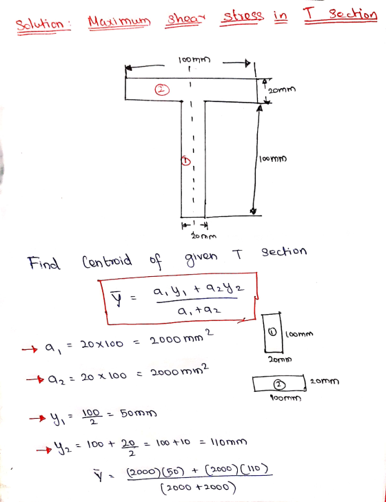
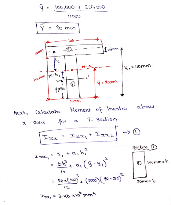
4. A T-shaped cross-sectional beam is loaded as shown in the figure. Determine the following a....
 4. A T-shaped cross-sectional beam is loaded as shown in the figure. Determine the following a. Sketch the internal shear force and bending moment diagrams for the beam. b. Calculate the maximum magnitude of the bending stress. Indicate where this occurs on the cross-section and along the length of the beam. c. Calculate the transverse shearing stress at the centroid of the cross-section using the maximum magnitude of the transverse shear force. - 200 mm 8 KN 1.5 kN/m 20...
The internal shear force at a certain section of a steel beam is V=185 kN. The...
 The internal shear force at a certain section of a steel beam is
V=185 kN. The beam cross section shown in the figure has dimensions
of tf=17 mm, bf=300 mm, d=394 mm, and tw=10 mm. Determine:
(a) the shear stress at point A, which is located at
yA=71 mm below the centroid of the wide-flange shape.
(b) the maximum horizontal shear stress in the wide-flange
shape.
The internal shear force at a certain section of a steel beam is V=...
The internal shear force at a certain section of a steel beam is
V=185 kN. The beam cross section shown in the figure has dimensions
of tf=17 mm, bf=300 mm, d=394 mm, and tw=10 mm. Determine:
(a) the shear stress at point A, which is located at
yA=71 mm below the centroid of the wide-flange shape.
(b) the maximum horizontal shear stress in the wide-flange
shape.
The internal shear force at a certain section of a steel beam is V=...
V = 118 KN A beam with the cross-section shown is carrying a vertical shear force...
 V = 118 KN
A beam with the cross-section shown is carrying a vertical shear force of magnitude v. 15mm It has already been calculated that: the neutral plane is 29 mm above the bottom face, and the second moment of area is / = 8.121x10⁷ m (you do not need to re-calculate these values), NP7 29mn 28m mm Isom a) Indicate on the drawing above, where the shear stress () in the beam will be the greatest? b) Calculate...
V = 118 KN
A beam with the cross-section shown is carrying a vertical shear force of magnitude v. 15mm It has already been calculated that: the neutral plane is 29 mm above the bottom face, and the second moment of area is / = 8.121x10⁷ m (you do not need to re-calculate these values), NP7 29mn 28m mm Isom a) Indicate on the drawing above, where the shear stress () in the beam will be the greatest? b) Calculate...
PLEASE PRINT Question Four The beam has a cross section shown below and is subjected to...
 PLEASE PRINT
Question Four The beam has a cross section shown below and is subjected to a 1 kN load as shown. The beam AB has a length of 3 m. a) Draw the shear force and bending moment diagrams. b) Determine the maximum bending stress. c) Where is the location of the maximum stress in b) above? 30 mm 30 mm 30 mm 50 mm t 40 mm 50 m 40mm
PLEASE PRINT
Question Four The beam has a cross section shown below and is subjected to a 1 kN load as shown. The beam AB has a length of 3 m. a) Draw the shear force and bending moment diagrams. b) Determine the maximum bending stress. c) Where is the location of the maximum stress in b) above? 30 mm 30 mm 30 mm 50 mm t 40 mm 50 m 40mm
A rectangular beam is subjected to the loadings shown in Figure Q.16(a) has cross section of...
 A rectangular beam is subjected to the loadings shown in Figure Q.16(a) has cross section of 100 mm x 300 mm as shown in Figure Q.16(b). An axial load of 5 kN is applied along the centroid of the cross-section at one end of the beam. Compute the normal stress and shear stress at point P through the cut-section of P in the beam. [15 marks] у 10 kN/m P Ž 5 KN --- 00 P k 3 m -...
The internal shear force at a certain section of a steel beam is V = 240...
 The internal shear force at a certain section of a steel beam is V = 240 kN. The beam cross section shown in the figure has dimensions of t; = 18 mm, by = 305 mm, d = 374 mm, and t = 11 mm. Determine: (a) the shear stress at point A, which is located at y; = 74 mm below the centroid of the wide-flange shape. (b) the maximum horizontal shear stress in the wide-flange shape. To VA...
Q211 A steel beam has Z-bar cross section as shown in below. Here O is the...
 Q211 A steel beam has Z-bar cross section as shown in below. Here O is the centroid of the cross section Moment of inertia and product of inertia of the cross section are given by I, = 24.3960(10° ) mm. l, = 67.41 10(10° ) mm. 1,--30.1840(10° ) mm. The internal force developed in the cross section is M 12 kN-m as shown. Determine the location and magnitude of the maximum tensile stress and maximum compressive stress in the cross...
Figure 1 shows the cross section of a lipped channel. The cross section carries a shear force of ...
 Figure 1 shows the cross section of a lipped channel. The cross section carries a shear force of 250 kN acting at 45° below the major principal axis (as shown) and through the shear centre. Determine the (Ans: 134.1 MPa) maximum shear stress. (Use line of mid-thickness properties) た45 S.c 4250 N たA 100 Figure 1
Figure 1 shows the cross section of a lipped channel. The cross section carries a shear force of 250 kN acting at 45° below...
Figure 1 shows the cross section of a lipped channel. The cross section carries a shear force of 250 kN acting at 45° below the major principal axis (as shown) and through the shear centre. Determine the (Ans: 134.1 MPa) maximum shear stress. (Use line of mid-thickness properties) た45 S.c 4250 N たA 100 Figure 1
Figure 1 shows the cross section of a lipped channel. The cross section carries a shear force of 250 kN acting at 45° below...
 Q.1) The cross-section shown below of a simply supported beam is subjected to a maximum shear force of 20 kN. Determine the corresponding shearing stress at points a and b. Also determine the maximum shear stress in the cross- section and state its location 40 mm 4 mm 60 mm 14 mm 4 mm 20 mm 28 mm 20 mm
 The beam has the loading and the shear diagram as shown. Consider a cross section between C and D, determine: • the maximum shearing stress in that cross section, • the shearing stress at point Hon the web of the beam at the same cross section. 15 kN 8 KN 9 KN 12 KN -180 mm 40 mm А B C D E F H 3 m + 2m +2 m-42 m 4 m T 180 mm 12 KN 9...
 4. A T-shaped cross-sectional beam is loaded as shown in the figure. Determine the following a. Sketch the internal shear force and bending moment diagrams for the beam. b. Calculate the maximum magnitude of the bending stress. Indicate where this occurs on the cross-section and along the length of the beam. c. Calculate the transverse shearing stress at the centroid of the cross-section using the maximum magnitude of the transverse shear force. - 200 mm 8 KN 1.5 kN/m 20...
 The internal shear force at a certain section of a steel beam is
V=185 kN. The beam cross section shown in the figure has dimensions
of tf=17 mm, bf=300 mm, d=394 mm, and tw=10 mm. Determine:
(a) the shear stress at point A, which is located at
yA=71 mm below the centroid of the wide-flange shape.
(b) the maximum horizontal shear stress in the wide-flange
shape.
The internal shear force at a certain section of a steel beam is V=...
The internal shear force at a certain section of a steel beam is
V=185 kN. The beam cross section shown in the figure has dimensions
of tf=17 mm, bf=300 mm, d=394 mm, and tw=10 mm. Determine:
(a) the shear stress at point A, which is located at
yA=71 mm below the centroid of the wide-flange shape.
(b) the maximum horizontal shear stress in the wide-flange
shape.
The internal shear force at a certain section of a steel beam is V=...
 V = 118 KN
A beam with the cross-section shown is carrying a vertical shear force of magnitude v. 15mm It has already been calculated that: the neutral plane is 29 mm above the bottom face, and the second moment of area is / = 8.121x10⁷ m (you do not need to re-calculate these values), NP7 29mn 28m mm Isom a) Indicate on the drawing above, where the shear stress () in the beam will be the greatest? b) Calculate...
V = 118 KN
A beam with the cross-section shown is carrying a vertical shear force of magnitude v. 15mm It has already been calculated that: the neutral plane is 29 mm above the bottom face, and the second moment of area is / = 8.121x10⁷ m (you do not need to re-calculate these values), NP7 29mn 28m mm Isom a) Indicate on the drawing above, where the shear stress () in the beam will be the greatest? b) Calculate...
 PLEASE PRINT
Question Four The beam has a cross section shown below and is subjected to a 1 kN load as shown. The beam AB has a length of 3 m. a) Draw the shear force and bending moment diagrams. b) Determine the maximum bending stress. c) Where is the location of the maximum stress in b) above? 30 mm 30 mm 30 mm 50 mm t 40 mm 50 m 40mm
PLEASE PRINT
Question Four The beam has a cross section shown below and is subjected to a 1 kN load as shown. The beam AB has a length of 3 m. a) Draw the shear force and bending moment diagrams. b) Determine the maximum bending stress. c) Where is the location of the maximum stress in b) above? 30 mm 30 mm 30 mm 50 mm t 40 mm 50 m 40mm
 A rectangular beam is subjected to the loadings shown in Figure Q.16(a) has cross section of 100 mm x 300 mm as shown in Figure Q.16(b). An axial load of 5 kN is applied along the centroid of the cross-section at one end of the beam. Compute the normal stress and shear stress at point P through the cut-section of P in the beam. [15 marks] у 10 kN/m P Ž 5 KN --- 00 P k 3 m -...
 The internal shear force at a certain section of a steel beam is V = 240 kN. The beam cross section shown in the figure has dimensions of t; = 18 mm, by = 305 mm, d = 374 mm, and t = 11 mm. Determine: (a) the shear stress at point A, which is located at y; = 74 mm below the centroid of the wide-flange shape. (b) the maximum horizontal shear stress in the wide-flange shape. To VA...
 Q211 A steel beam has Z-bar cross section as shown in below. Here O is the centroid of the cross section Moment of inertia and product of inertia of the cross section are given by I, = 24.3960(10° ) mm. l, = 67.41 10(10° ) mm. 1,--30.1840(10° ) mm. The internal force developed in the cross section is M 12 kN-m as shown. Determine the location and magnitude of the maximum tensile stress and maximum compressive stress in the cross...
 Figure 1 shows the cross section of a lipped channel. The cross section carries a shear force of 250 kN acting at 45° below the major principal axis (as shown) and through the shear centre. Determine the (Ans: 134.1 MPa) maximum shear stress. (Use line of mid-thickness properties) た45 S.c 4250 N たA 100 Figure 1
Figure 1 shows the cross section of a lipped channel. The cross section carries a shear force of 250 kN acting at 45° below...
Figure 1 shows the cross section of a lipped channel. The cross section carries a shear force of 250 kN acting at 45° below the major principal axis (as shown) and through the shear centre. Determine the (Ans: 134.1 MPa) maximum shear stress. (Use line of mid-thickness properties) た45 S.c 4250 N たA 100 Figure 1
Figure 1 shows the cross section of a lipped channel. The cross section carries a shear force of 250 kN acting at 45° below...
Most questions answered within 3 hours.
-
Perform encryption and decryption using RSA algorithm for the
following
P= 5; q = 11, M=...
asked 10 minutes ago -
The mass Tris base for 100mL of a 0.1M solution is
121.1g . Use the Henderson-Hasselbalch...
asked 2 minutes ago -
Given the following data from Swamp & Sand Industries,
calculate the NI. The tax rate is...
asked 6 minutes ago -
Suppose we mix 1 mole each of Cl2(g) and Cl(g) at 298K, 1 bar.
Which way...
asked 3 minutes ago -
How
many 14 AWG THW conductors are permitted in a 3 in x 2 in x...
asked 8 minutes ago -
1. Summarize"Soils of the Tropics and the World Food Crisis" the
article in a paragraph, making...
asked 8 minutes ago -
Say that you are looking to build a structure (home or something
else of interest) on...
asked 8 minutes ago -
1(a). Draw both chair conformations of
trans-1-chloro-2-methylcyclohexane. Compare stabilities. (b) .Draw
both chair conformations of cis-1-...
asked 19 minutes ago -
Which of the following is true regarding stakeholders?
A. The term stakeholder is a variant of...
asked 17 minutes ago -
Graph the mean winning margins for years 2005 - 2007 for women's
NCAA Basketball tournaments. Is...
asked 27 minutes ago -
The equilibrium constant, K, of a certain first order reaction
was measured at two temperatures, T....
asked 26 minutes ago -
Management by walking around (MBWA) refers to
a. the process used by new executives to get...
asked 39 minutes ago