
Homework Answers

Add Answer to:
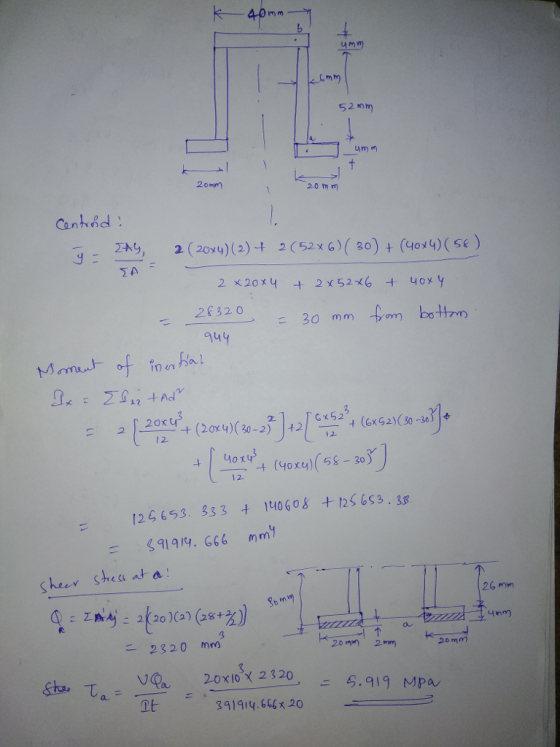
Q.1) The cross-section shown below of a simply supported beam is subjected to a maximum shear...
The simply supported beam, with a U cross section, is subjected to a uniformly distributed force...
 The simply supported beam, with a U cross section, is subjected to a uniformly distributed force of 8 kN/m and a concentrated load of 12 kN as shown. (a) Determine the reaction at supports A and B, (b) sketch the shear diagram and the moment diagram, (c) determine the location of the neutral axis of the cross section and calculate its area moment of inertia about the neutral axis, and (d) determine absolute maximum bending stress and (e) absolute maximum...
A cantilever beam, with a rectangular cross section, is subjected to loads P, Q and R,...
 A cantilever beam, with a rectangular cross section, is subjected to loads P, Q and R, as illustrated in the figure below. Given, P 100 kN, Q 15 kN and R 10 kN, determine the principal stresses and the maximum in-plane shearing stress at point B. Also, determine the planes on which the principal stresses act, and the planes on which the maximum in-plane shear stress acts. The vertical dimension (depth) of the beam is 120 mm. 40 mmA 2...
A simply supported beam is subjected to a load applied as shown in the figure. Draw the shear for...
 A simply supported beam is subjected to a load applied as shown in the figure. Draw the shear force diagram. Consider the section shown and determine (a) the largest shear stress in the section n-n, (b) the shear stress at point a and show this stress on an element. 15,15 30 15,15 20 I n 40 120 15m 0.8 m Dimensions in mm
A simply supported beam is subjected to a load applied as shown in the figure. Draw the...
A simply supported beam is subjected to a load applied as shown in the figure. Draw the shear force diagram. Consider the section shown and determine (a) the largest shear stress in the section n-n, (b) the shear stress at point a and show this stress on an element. 15,15 30 15,15 20 I n 40 120 15m 0.8 m Dimensions in mm
A simply supported beam is subjected to a load applied as shown in the figure. Draw the...
The beam has the loading and the shear diagram as shown. Consider a cross section between...
 The beam has the loading and the shear diagram as shown. Consider a cross section between C and D, determine: • the maximum shearing stress in that cross section, • the shearing stress at point Hon the web of the beam at the same cross section. 15 kN 8 KN 9 KN 12 KN -180 mm 40 mm А B C D E F H 3 m + 2m +2 m-42 m 4 m T 180 mm 12 KN 9...
PLEASE PRINT Question Four The beam has a cross section shown below and is subjected to...
 PLEASE PRINT
Question Four The beam has a cross section shown below and is subjected to a 1 kN load as shown. The beam AB has a length of 3 m. a) Draw the shear force and bending moment diagrams. b) Determine the maximum bending stress. c) Where is the location of the maximum stress in b) above? 30 mm 30 mm 30 mm 50 mm t 40 mm 50 m 40mm
PLEASE PRINT
Question Four The beam has a cross section shown below and is subjected to a 1 kN load as shown. The beam AB has a length of 3 m. a) Draw the shear force and bending moment diagrams. b) Determine the maximum bending stress. c) Where is the location of the maximum stress in b) above? 30 mm 30 mm 30 mm 50 mm t 40 mm 50 m 40mm
A concentrated force P is applied in the middle of a simply supported beam with the T-shaped cross section shown. The m...
 A concentrated force P is applied in the middle of a simply supported beam with the T-shaped cross section shown. The maximum value of the load P so that the normal stress in the beam does not exceed 25 MPa is most closely: 150 mm P 30 mm 4m 4m 120 mm A' B A 40 mm A. 3.1 kN B. 5.8 kN Oc. 2.5 kN D. 4.3 kN
A concentrated force P is applied in the middle of a...
A concentrated force P is applied in the middle of a simply supported beam with the T-shaped cross section shown. The maximum value of the load P so that the normal stress in the beam does not exceed 25 MPa is most closely: 150 mm P 30 mm 4m 4m 120 mm A' B A 40 mm A. 3.1 kN B. 5.8 kN Oc. 2.5 kN D. 4.3 kN
A concentrated force P is applied in the middle of a...
A 5-m-long simply supported timber beam carries two concentrated loads as shown dimensions of the beam...
 A 5-m-long simply supported timber beam carries two concentrated loads as shown dimensions of the beam are shown a) At section a-a e the magnitude of the shear stress in the beam at point H. -7748 KNIm in the beam at point K the beam, at any location within the 5-m span length. V occurs in the beam at any location within the 5-m span length.)diagr. the magnitude of the shear stress (b) At section a-a, (e) Determine the maximum...
If a simply supported beam is subjected to the following loading and across section of the beam is provided
If a simply supported beam is subjected to the following loading and across section of the beam is provided, determine the following a. Determine the maximum bending stress in the beam. b. Determine the absolute maximum shear stress in the beam.
5. A beam has the cross-section as shown in the figure. If the shear force at...
 5. A beam has the cross-section as shown in the figure. If the shear force at a section is 24.6 KN, find the maximum shear stress and its location. 100 mm 20 mm T 100 mm 20mm
1. For the simply supported beam subjected to the loading shown, Derive equations for the shear...
 1. For the simply supported beam subjected to the loading shown, Derive equations for the shear force V and the bending moment M for any location in the beam. (Place the origin at point A.) a. b. Plot the shear-force and bending-moment diagrams for the beam using the derived functions c. Report the maximum bending moment and its location. 42 kips 6 kips/ft 10 ft 20 ft
 A cantilever beam, with a rectangular cross section, is subjected to loads P, Q and R, as illustrated in the figure below. Given, P 100 kN, Q 15 kN and R 10 kN, determine the principal stresses and the maximum in-plane shearing stress at point B. Also, determine the planes on which the principal stresses act, and the planes on which the maximum in-plane shear stress acts. The vertical dimension (depth) of the beam is 120 mm. 40 mmA 2...
 A simply supported beam is subjected to a load applied as shown in the figure. Draw the shear force diagram. Consider the section shown and determine (a) the largest shear stress in the section n-n, (b) the shear stress at point a and show this stress on an element. 15,15 30 15,15 20 I n 40 120 15m 0.8 m Dimensions in mm
A simply supported beam is subjected to a load applied as shown in the figure. Draw the...
A simply supported beam is subjected to a load applied as shown in the figure. Draw the shear force diagram. Consider the section shown and determine (a) the largest shear stress in the section n-n, (b) the shear stress at point a and show this stress on an element. 15,15 30 15,15 20 I n 40 120 15m 0.8 m Dimensions in mm
A simply supported beam is subjected to a load applied as shown in the figure. Draw the...
 The beam has the loading and the shear diagram as shown. Consider a cross section between C and D, determine: • the maximum shearing stress in that cross section, • the shearing stress at point Hon the web of the beam at the same cross section. 15 kN 8 KN 9 KN 12 KN -180 mm 40 mm А B C D E F H 3 m + 2m +2 m-42 m 4 m T 180 mm 12 KN 9...
 PLEASE PRINT
Question Four The beam has a cross section shown below and is subjected to a 1 kN load as shown. The beam AB has a length of 3 m. a) Draw the shear force and bending moment diagrams. b) Determine the maximum bending stress. c) Where is the location of the maximum stress in b) above? 30 mm 30 mm 30 mm 50 mm t 40 mm 50 m 40mm
PLEASE PRINT
Question Four The beam has a cross section shown below and is subjected to a 1 kN load as shown. The beam AB has a length of 3 m. a) Draw the shear force and bending moment diagrams. b) Determine the maximum bending stress. c) Where is the location of the maximum stress in b) above? 30 mm 30 mm 30 mm 50 mm t 40 mm 50 m 40mm
 A concentrated force P is applied in the middle of a simply supported beam with the T-shaped cross section shown. The maximum value of the load P so that the normal stress in the beam does not exceed 25 MPa is most closely: 150 mm P 30 mm 4m 4m 120 mm A' B A 40 mm A. 3.1 kN B. 5.8 kN Oc. 2.5 kN D. 4.3 kN
A concentrated force P is applied in the middle of a...
A concentrated force P is applied in the middle of a simply supported beam with the T-shaped cross section shown. The maximum value of the load P so that the normal stress in the beam does not exceed 25 MPa is most closely: 150 mm P 30 mm 4m 4m 120 mm A' B A 40 mm A. 3.1 kN B. 5.8 kN Oc. 2.5 kN D. 4.3 kN
A concentrated force P is applied in the middle of a...
 A 5-m-long simply supported timber beam carries two concentrated loads as shown dimensions of the beam are shown a) At section a-a e the magnitude of the shear stress in the beam at point H. -7748 KNIm in the beam at point K the beam, at any location within the 5-m span length. V occurs in the beam at any location within the 5-m span length.)diagr. the magnitude of the shear stress (b) At section a-a, (e) Determine the maximum...
 5. A beam has the cross-section as shown in the figure. If the shear force at a section is 24.6 KN, find the maximum shear stress and its location. 100 mm 20 mm T 100 mm 20mm
 1. For the simply supported beam subjected to the loading shown, Derive equations for the shear force V and the bending moment M for any location in the beam. (Place the origin at point A.) a. b. Plot the shear-force and bending-moment diagrams for the beam using the derived functions c. Report the maximum bending moment and its location. 42 kips 6 kips/ft 10 ft 20 ft
Most questions answered within 3 hours.
-
2) You are given the task of finding a representation for a
circle in a drawing...
asked 20 minutes ago -
STUDY QUESTION: Does use of diet drug fen-phen
(fenfluramine-phentermine) cause valvular heart disease?
HINT: Valvular heart...
asked 12 minutes ago -
1. An object weighing 40 N rests on a surface. The coefficient
of friction is 0.35....
asked 1 hour ago -
Investor company owns 35% of investee company voting stock and
accounts for the investment under the...
asked 2 hours ago -
The number of major faults on a randomly chosen 1 km stretch of
highway has a...
asked 2 hours ago -
Consider the competitive environment of Starbuck's, Progressive
Insurance, a manufacturing firm with low turnover, or a...
asked 3 hours ago -
3. Gains from trade
Consider two neighbouring island countries called Euphoria and
Contente. They each have...
asked 5 hours ago -
A business executive has the option to invest money in two
plans: Plan A guarantees that...
asked 7 hours ago -
Hello, can someone please help me answer this question?
How much heat is absorbed by a...
asked 7 hours ago -
. A marketing researcher conducted a survey of 25 shoppers
randomly selected at the local mall...
asked 8 hours ago -
Create an comprehensive response to the
following:
Antimicrobial agents work on a multitude of microbes (bacteria,...
asked 8 hours ago -
6.13 LAB: Step counter. Section 6.3.
A pedometer treats walking 2,000 steps as walking 1 mile....
asked 8 hours ago