

Homework Answers


Add Answer to:
P4.3: The crank-slider offset mechanism shown in Figure P4.3 has the link lengths: Las - 4",...
P4.2: The four-bar mechanism in Figure P4.2 has the link lengths: LAB = 4", LED =...
 P4.2: The four-bar mechanism in Figure P4.2 has the link lengths: LAB = 4", LED = 24", Loc = 14", LA = 30". The location of COM is as follows: LAG = 2.120"; LEG2 = 11.863"; LDG = 6.722". The crank 1 rotates counterclockwise with the angular displacement 8. = 27t-t [rad), angular velocity 0. = , = 21 [rad/s], and angular accelera- tion &= 7= 0 [rad/s). The mass and moment of inertia relative to each link's COM are...
Part A Q1: The crank OP of a mechanism as shown in figure below rotates uniformly...
 Part A
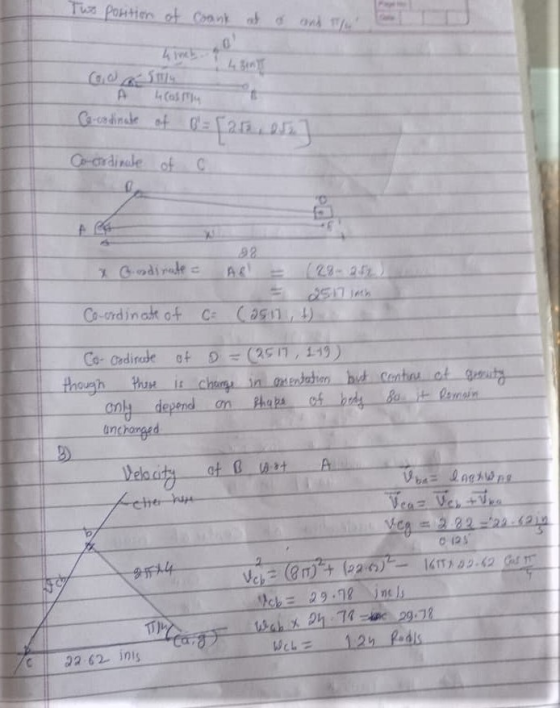
Q1: The crank OP of a mechanism as shown in figure below rotates uniformly at 60 rpm counter-clockwise. Various links have following dimensions: OP = 50 mm; RQ= 200 mm; RS = 200 mm; PR = 300 mm a) Make appropriate scale to draw position diagram using graphical method. b) Find the linear velocities (mm/sec) and angular velocities (rad/sec) for all links and draw velocity diagram. c) Find the tangential accelerations (mm/sec) and radial acceleration (mm/sec) and angular...
Part A
Q1: The crank OP of a mechanism as shown in figure below rotates uniformly at 60 rpm counter-clockwise. Various links have following dimensions: OP = 50 mm; RQ= 200 mm; RS = 200 mm; PR = 300 mm a) Make appropriate scale to draw position diagram using graphical method. b) Find the linear velocities (mm/sec) and angular velocities (rad/sec) for all links and draw velocity diagram. c) Find the tangential accelerations (mm/sec) and radial acceleration (mm/sec) and angular...
Q1: The crank OP of a mechanism as shown in figure below rotates uniformly at 60...
 Q1: The crank OP of a mechanism as shown in figure below rotates uniformly at 60 rpm counter-clockwise. Various links have following dimensions: OP - 50 mm; RQ-200 mm; RS - 200 mm; PR = 300 mm a) Make appropriate scale to draw position diagram using graphical method. b) Find the linear velosities (mm/sec) and angular velosities (rad/sec) for all links and draw velocity diagram. c) Find the tangential accelerations (mm/sec) and radial acceleration (mm/sec) and angular accelerations (rad/sec) for...
2. The crank AB rotates counter-clockwise with the angular velocity of 10 rad/s. The piston is...
 2. The crank AB rotates counter-clockwise with the angular velocity of 10 rad/s. The piston is displaced with da = 7.803 in from home position Co. The home position of the piston is yco = 43.803”. The unit vector of the sliding direction is: u Determine: (50 pts) u © - = 7.803 in DO-+c 2 in 24 in в (о 12 in А Write the coordinates of all joints and COM. Assume the COM is in the center of...
DYNAMICS An internal combustion engine slider-crank mechanism is shown in the figure. Crank AB rotates in...
 DYNAMICS
An internal combustion engine slider-crank mechanism is shown in the figure. Crank AB rotates in selected clockwise positive direction as shown. Piston position is Y=AD. e(t) is angular position of the crank, ó(t) is angular velocity of the crank, ő is angular acceleration of the crank, y Р D 150 mm А e B - - X 50 mm 5) Crank AB rotates starting from rest with a constant angular acceleration of 0.25 rad/sec? ( = 0.25 rad/sec? )...
DYNAMICS
An internal combustion engine slider-crank mechanism is shown in the figure. Crank AB rotates in selected clockwise positive direction as shown. Piston position is Y=AD. e(t) is angular position of the crank, ó(t) is angular velocity of the crank, ő is angular acceleration of the crank, y Р D 150 mm А e B - - X 50 mm 5) Crank AB rotates starting from rest with a constant angular acceleration of 0.25 rad/sec? ( = 0.25 rad/sec? )...
3. Link 2 (AB) of the slider crank inversion shown in Figure 3 is rotating at a constant 2 11.00k(rad/s). Determine the angular velocity of link 4 (DC) at the instant shown in the figure. Hints: The...
 3. Link 2 (AB) of the slider crank inversion shown in Figure 3 is rotating at a constant 2 11.00k(rad/s). Determine the angular velocity of link 4 (DC) at the instant shown in the figure. Hints: The angle between links 3 and 4 is fized so they have the same angular velocity. Consider Cs as point on Link 3 sliding through the bearing on link 4. (100 points) C3 90° A = (0,0). Figure 3: Slider crank inversion. (110.09,0) cm....
An internal combustion engine slider-crank mechanism is shown in the figure. Crank AB rotates in selected...
 An internal combustion engine slider-crank mechanism is shown in the figure. Crank AB rotates in selected clockwise positive direction as shown. Piston position is Y=AD. e(t) is angular position of the crank, ó(t) is angular velocity of the crank, ő is angular acceleration of the crank, 4) Crank AB rotates starting from rest with a constant angular acceleration of 0.25 rad/sec? ( = 0.25 rad/sec² ) clockwise in positive 0 direction as shown Perform computer simulations using above formulas to...
Question 4 (15 marks) The figure below shows a slider-crank mechanism. Link AB is driven with...
 Question 4 (15 marks) The figure below shows a slider-crank mechanism. Link AB is driven with a CONSTANT angular velocity of 4 rad/s. a) Determine the (vector) velocity of point B. b) Determine the angular velocity of link BC and the velocity of the slider at C. c) Determine the (vector) acceleration of point B. d) Determine the (vector) acceleration of the slider at C. 125 mm MAB = 4 rad/s 300 mm 600
For the slider-crank arrangement shown in the figure, a-3", b - 8" and c 0. The...
 For the slider-crank arrangement shown in the figure, a-3", b - 8" and c 0. The crank O2-A is being rotated by a constant speed motor at a rate of 1 rad/s. Based on the kinematic analysis of this arrangement, it is observed that when 02 60°, 03- 108.96° and o3--0.58 rad/s2 and a3 0.02 rad/s2. Assume that links O2-A and A-B are linear and their centers of gravity falls at the middle of the lines connecting those points. ABA...
Question + 130 marks An inverted low. The -10 in totales verted crank-slider mechanism is shown...
 Question + 130 marks An inverted low. The -10 in totales verted crank-slider mechanism is shown below. The ground link makes angle of 25° with the izontal line as shown. The crank rotates at a constant angular velocity of 300 rad/sec (CCW). Mechanism dimensions are 10 inches, F. 40 inches a) Choose a proper angle for the angular orientation of the follower (link 4) and the coupler (link) 0, 0, and conduct the displacement analysis by means of the loop.closure...
 P4.2: The four-bar mechanism in Figure P4.2 has the link lengths: LAB = 4", LED = 24", Loc = 14", LA = 30". The location of COM is as follows: LAG = 2.120"; LEG2 = 11.863"; LDG = 6.722". The crank 1 rotates counterclockwise with the angular displacement 8. = 27t-t [rad), angular velocity 0. = , = 21 [rad/s], and angular accelera- tion &= 7= 0 [rad/s). The mass and moment of inertia relative to each link's COM are...
 Part A
Q1: The crank OP of a mechanism as shown in figure below rotates uniformly at 60 rpm counter-clockwise. Various links have following dimensions: OP = 50 mm; RQ= 200 mm; RS = 200 mm; PR = 300 mm a) Make appropriate scale to draw position diagram using graphical method. b) Find the linear velocities (mm/sec) and angular velocities (rad/sec) for all links and draw velocity diagram. c) Find the tangential accelerations (mm/sec) and radial acceleration (mm/sec) and angular...
Part A
Q1: The crank OP of a mechanism as shown in figure below rotates uniformly at 60 rpm counter-clockwise. Various links have following dimensions: OP = 50 mm; RQ= 200 mm; RS = 200 mm; PR = 300 mm a) Make appropriate scale to draw position diagram using graphical method. b) Find the linear velocities (mm/sec) and angular velocities (rad/sec) for all links and draw velocity diagram. c) Find the tangential accelerations (mm/sec) and radial acceleration (mm/sec) and angular...
 Q1: The crank OP of a mechanism as shown in figure below rotates uniformly at 60 rpm counter-clockwise. Various links have following dimensions: OP - 50 mm; RQ-200 mm; RS - 200 mm; PR = 300 mm a) Make appropriate scale to draw position diagram using graphical method. b) Find the linear velosities (mm/sec) and angular velosities (rad/sec) for all links and draw velocity diagram. c) Find the tangential accelerations (mm/sec) and radial acceleration (mm/sec) and angular accelerations (rad/sec) for...
 2. The crank AB rotates counter-clockwise with the angular velocity of 10 rad/s. The piston is displaced with da = 7.803 in from home position Co. The home position of the piston is yco = 43.803”. The unit vector of the sliding direction is: u Determine: (50 pts) u © - = 7.803 in DO-+c 2 in 24 in в (о 12 in А Write the coordinates of all joints and COM. Assume the COM is in the center of...
 DYNAMICS
An internal combustion engine slider-crank mechanism is shown in the figure. Crank AB rotates in selected clockwise positive direction as shown. Piston position is Y=AD. e(t) is angular position of the crank, ó(t) is angular velocity of the crank, ő is angular acceleration of the crank, y Р D 150 mm А e B - - X 50 mm 5) Crank AB rotates starting from rest with a constant angular acceleration of 0.25 rad/sec? ( = 0.25 rad/sec? )...
DYNAMICS
An internal combustion engine slider-crank mechanism is shown in the figure. Crank AB rotates in selected clockwise positive direction as shown. Piston position is Y=AD. e(t) is angular position of the crank, ó(t) is angular velocity of the crank, ő is angular acceleration of the crank, y Р D 150 mm А e B - - X 50 mm 5) Crank AB rotates starting from rest with a constant angular acceleration of 0.25 rad/sec? ( = 0.25 rad/sec? )...
 3. Link 2 (AB) of the slider crank inversion shown in Figure 3 is rotating at a constant 2 11.00k(rad/s). Determine the angular velocity of link 4 (DC) at the instant shown in the figure. Hints: The angle between links 3 and 4 is fized so they have the same angular velocity. Consider Cs as point on Link 3 sliding through the bearing on link 4. (100 points) C3 90° A = (0,0). Figure 3: Slider crank inversion. (110.09,0) cm....
 An internal combustion engine slider-crank mechanism is shown in the figure. Crank AB rotates in selected clockwise positive direction as shown. Piston position is Y=AD. e(t) is angular position of the crank, ó(t) is angular velocity of the crank, ő is angular acceleration of the crank, 4) Crank AB rotates starting from rest with a constant angular acceleration of 0.25 rad/sec? ( = 0.25 rad/sec² ) clockwise in positive 0 direction as shown Perform computer simulations using above formulas to...
 Question 4 (15 marks) The figure below shows a slider-crank mechanism. Link AB is driven with a CONSTANT angular velocity of 4 rad/s. a) Determine the (vector) velocity of point B. b) Determine the angular velocity of link BC and the velocity of the slider at C. c) Determine the (vector) acceleration of point B. d) Determine the (vector) acceleration of the slider at C. 125 mm MAB = 4 rad/s 300 mm 600
 For the slider-crank arrangement shown in the figure, a-3", b - 8" and c 0. The crank O2-A is being rotated by a constant speed motor at a rate of 1 rad/s. Based on the kinematic analysis of this arrangement, it is observed that when 02 60°, 03- 108.96° and o3--0.58 rad/s2 and a3 0.02 rad/s2. Assume that links O2-A and A-B are linear and their centers of gravity falls at the middle of the lines connecting those points. ABA...
 Question + 130 marks An inverted low. The -10 in totales verted crank-slider mechanism is shown below. The ground link makes angle of 25° with the izontal line as shown. The crank rotates at a constant angular velocity of 300 rad/sec (CCW). Mechanism dimensions are 10 inches, F. 40 inches a) Choose a proper angle for the angular orientation of the follower (link 4) and the coupler (link) 0, 0, and conduct the displacement analysis by means of the loop.closure...
Most questions answered within 3 hours.
-
(Expected rate of return and risk) Carter Inc. is evaluating a
security. Calculate the investment’s expected...
asked 1 hour ago -
What specific indicators can point to lack of progress for
African Americans in American society?
asked 2 hours ago -
1-The Electrons in a beam are moving at 2.7×10⁸ m/s in an
electric field of 15000...
asked 2 hours ago -
A gas tank is a vertical cylinder. It has a radius of 1m, a
height of...
asked 2 hours ago -
Accent Software faces the following conditions. All of these
support Accent’s use of a market-penetration pricing...
asked 3 hours ago -
A mathematically inclined friend emails you the following
instructions: "Meet me in the cafeteria the first...
asked 3 hours ago -
A monopoly sells in two countries . The demand curves in the two
countries are p1...
asked 4 hours ago -
A .15kg rubber ball is bounced off a wall. Before hitting the
wall, the ball moves...
asked 5 hours ago -
A manufacturing company preparing to build a new plant is
considering three potential locations for it....
asked 5 hours ago -
B. If compound Y has approximately the same values of solubility
in toluene as compound X,...
asked 6 hours ago -
Oscar Inc. has inventory in Japan valued at 39,051,000 Yen one
year ago. One year ago...
asked 6 hours ago -
If Canada suffered from "fundamental disequilibrium," and its
government choose not to devalue its currency, a...
asked 6 hours ago