
Homework Answers


Add Answer to:
Question 7 The state of plane stress at a point on the surface of a structural...
Question 6 The state of plane stress at a point on the surface of a structural...
 Question 6 The state of plane stress at a point on the surface of a structural element is represented on an unrotated element as shown. 110 psi 40 psi 90 psi I The max/min shear stresses are most nearly: 104 psi and -24 psi 90 psi and -10 psi 40 psi and -40 psi 64 psi and -64 psi
Question 4 The state of plane stress at a point on the surface of a structural...
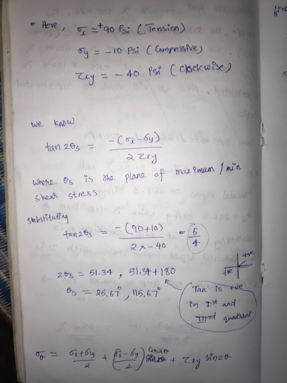
 Question 4 The state of plane stress at a point on the surface of a structural element is represented on an unrotated element as shown. 10 psi 40 psi 90 psi I The max/min shear stress angles (thetas) in degrees are most nearly: 19 and 109 -64 and -154 -19 and -109 64 and 154
Question 2 The state of plane stress at a point on the surface of a structural...
 Question 2 The state of plane stress at a point on the surface of a structural element is represented on an unrotated element as shown. (10 psi 40 psi 90 psi I The stresses on the X-face of a stress block rotated 45° counterclockwise are most nearly: 0 = 90 psi, T = -40 psi o = 80 psi, T = 50 psi O O = Opsi, T = -50 psi 0 0 = 47 psi , T =-64 psi
Question 5 The state of plane stress at a point on the surface of a structural...
 Question 5 The state of plane stress at a point on the surface of a structural element is represented on an unrotated element as shown. 10 psi 40 psi 90 psi I The principal stresses are most nearly: 64 psi and -64 psi 90 psi and -10 psi 40 psi and -40 psi
Question 3 The state of plane stress at a point on the surface of a structural...
 Question 3 The state of plane stress at a point on the surface of a structural element is represented on an unrotated element as shown. 110 psi 40 psi 90 psi I The principal stress angles (thetap) in degrees are most nearly: -64 and -154 64 and 154 19 and 109 -19 and -109
Question 1 The next several questions are based on the same unrotated stress block. The state...
 Question 1 The next several questions are based on the same unrotated stress block. The state of plane stress at a point on the surface of a structural element is represented on an unrotated element as shown. (10 psi 40 psi 90 psi I The coordinate of the center of a Mohr's Circle would be most nearly: O O = -10 psi, T = 40 psi O Cannot be determined O O = 40 psi, T = 0 psi O...
The state of plane stress at a point under the surface of the ANKA airplane wing...
 The state of plane stress at a point under the surface of the ANKA airplane wing is represented on the element oriented as shown in the Figure. Deternine principal Stresses Calculate the maximum in-plane shear stress and associated average normal stress by using the analytical method and Mohr's circle. For each case, determine the corresponding orientation of the element with respect to the element shown and sketch the state of stress on the element. Determine the absolute maximum shear stress...
O Due to an applied loading, an element at the point on a machine shaft is...
 O Due to an applied loading, an element at the point on a machine shaft is subjected to the state of plane stress shown in the figure. O Determine the principal stresses and the absolute maximum shear stress at the point Ox = –20 psi, Oy = Opsi, Txy = -40 psi . 20 psi 40 psi
9-16 The state of stress at a point is shown on the ele- ment. Determine (a) the principal stresses and (b) the max- imum in-plane shear stress and average normal stress at the point. Specify the ori...
 9-16 The state of stress at a point is shown on the ele- ment. Determine (a) the principal stresses and (b) the max- imum in-plane shear stress and average normal stress at the point. Specify the orientation of the element in each case. 250 MPa 175 MPa 200 MPa Prob. 9-16
9-16 The state of stress at a point is shown on the ele- ment. Determine (a) the principal stresses and (b) the max- imum in-plane shear stress and average...
9-16 The state of stress at a point is shown on the ele- ment. Determine (a) the principal stresses and (b) the max- imum in-plane shear stress and average normal stress at the point. Specify the orientation of the element in each case. 250 MPa 175 MPa 200 MPa Prob. 9-16
9-16 The state of stress at a point is shown on the ele- ment. Determine (a) the principal stresses and (b) the max- imum in-plane shear stress and average...
23 Mohrs circle The state of plane stress at a point is represented by the element...
 23 Mohrs circle The state of plane stress at a point is represented by the element shown in Fig. 2.2. Determine maximum shear stresses and the orientation, draw the stress element with the proper orientation. Determine principal stresses and the orientation, draw the stress element with the proper orientation (Note: this question is required to be solved using Mohrs circle.) Mohrs circle The state of plane stress at a point is represented by the element shown in Fig. 2.2. Determine...
 Question 6 The state of plane stress at a point on the surface of a structural element is represented on an unrotated element as shown. 110 psi 40 psi 90 psi I The max/min shear stresses are most nearly: 104 psi and -24 psi 90 psi and -10 psi 40 psi and -40 psi 64 psi and -64 psi
 Question 4 The state of plane stress at a point on the surface of a structural element is represented on an unrotated element as shown. 10 psi 40 psi 90 psi I The max/min shear stress angles (thetas) in degrees are most nearly: 19 and 109 -64 and -154 -19 and -109 64 and 154
 Question 2 The state of plane stress at a point on the surface of a structural element is represented on an unrotated element as shown. (10 psi 40 psi 90 psi I The stresses on the X-face of a stress block rotated 45° counterclockwise are most nearly: 0 = 90 psi, T = -40 psi o = 80 psi, T = 50 psi O O = Opsi, T = -50 psi 0 0 = 47 psi , T =-64 psi
 Question 5 The state of plane stress at a point on the surface of a structural element is represented on an unrotated element as shown. 10 psi 40 psi 90 psi I The principal stresses are most nearly: 64 psi and -64 psi 90 psi and -10 psi 40 psi and -40 psi
 Question 3 The state of plane stress at a point on the surface of a structural element is represented on an unrotated element as shown. 110 psi 40 psi 90 psi I The principal stress angles (thetap) in degrees are most nearly: -64 and -154 64 and 154 19 and 109 -19 and -109
 Question 1 The next several questions are based on the same unrotated stress block. The state of plane stress at a point on the surface of a structural element is represented on an unrotated element as shown. (10 psi 40 psi 90 psi I The coordinate of the center of a Mohr's Circle would be most nearly: O O = -10 psi, T = 40 psi O Cannot be determined O O = 40 psi, T = 0 psi O...
 The state of plane stress at a point under the surface of the ANKA airplane wing is represented on the element oriented as shown in the Figure. Deternine principal Stresses Calculate the maximum in-plane shear stress and associated average normal stress by using the analytical method and Mohr's circle. For each case, determine the corresponding orientation of the element with respect to the element shown and sketch the state of stress on the element. Determine the absolute maximum shear stress...
 O Due to an applied loading, an element at the point on a machine shaft is subjected to the state of plane stress shown in the figure. O Determine the principal stresses and the absolute maximum shear stress at the point Ox = –20 psi, Oy = Opsi, Txy = -40 psi . 20 psi 40 psi
 9-16 The state of stress at a point is shown on the ele- ment. Determine (a) the principal stresses and (b) the max- imum in-plane shear stress and average normal stress at the point. Specify the orientation of the element in each case. 250 MPa 175 MPa 200 MPa Prob. 9-16
9-16 The state of stress at a point is shown on the ele- ment. Determine (a) the principal stresses and (b) the max- imum in-plane shear stress and average...
9-16 The state of stress at a point is shown on the ele- ment. Determine (a) the principal stresses and (b) the max- imum in-plane shear stress and average normal stress at the point. Specify the orientation of the element in each case. 250 MPa 175 MPa 200 MPa Prob. 9-16
9-16 The state of stress at a point is shown on the ele- ment. Determine (a) the principal stresses and (b) the max- imum in-plane shear stress and average...
 23 Mohrs circle The state of plane stress at a point is represented by the element shown in Fig. 2.2. Determine maximum shear stresses and the orientation, draw the stress element with the proper orientation. Determine principal stresses and the orientation, draw the stress element with the proper orientation (Note: this question is required to be solved using Mohrs circle.) Mohrs circle The state of plane stress at a point is represented by the element shown in Fig. 2.2. Determine...
Most questions answered within 3 hours.
-
1a. The __________ functional group often triggers our sense of
smell.
1b. The geometry around a...
asked 1 minute from now -
Suppose a floor on a hospital has 12 physicians at any given
time. You are brought...
asked 13 minutes ago -
Compartmentalization
in eukaryotic cells facilitates chemical reactions happening faster
due to... Select all
Substrates needed for...
asked 21 seconds ago -
The deltaH for the solution process when solid sodium
hydroxide dissolves in water is 44.4 kJ/mol....
asked 3 minutes ago -
a. Discuss the reciprocal/opposite “hormonal” regulation of the
most highly regulated steps of these two pathways....
asked 21 minutes ago -
Members of unions had mounted campaigns to persuade customers
not to shop at a company because...
asked 22 minutes ago -
Why is the alpha carboxyl group pka value 2 ?
And why is an alpha amino...
asked 31 minutes ago -
Identify and assess an intrapreneurial
opportunities within Bank of America and
intrapreneurial assessment. Assess its impact...
asked 37 minutes ago -
How do I figure out the range of possible numbers that can be
represented by the...
asked 38 minutes ago -
A 0.48-kg metal sphere oscillates at the end of a vertical
spring. As the spring stretches...
asked 41 minutes ago -
If a block of Si is doped with 10^17 Boron atom/cm^3 and 5X10^16
Arsenic atoms/cm^3,
(a)...
asked 1 hour ago -
Why would natural selection not minimize costs (in the form of
symptoms) of evolved defenses? (choose...
asked 1 hour ago