
Homework Answers
Feel free to ask any question but remember to rate the answer.


Add Answer to:
The copper shaft is subjected to the axial loads shown in (Figure 1). Figure < 1...
14-2. The copper shaft is subjected to the axial loads shown. Determine the displacement of end...
 14-2. The copper shaft is subjected to the axial loads shown. Determine the displacement of end A with respect to end D if the diameters of each segment are dal = 0.75 in., dec=1 in., and dcp=0.5 in. Take Ecu = 18(109) ksi. -80 in.-- 5 kip 150 in.- +-100 in.--- 8 kip 2 kip 6 kip D 5 kip B C 2 kip Prob. 4-2
Part A Determine the displacement of end A with respect to and D if the diameters...
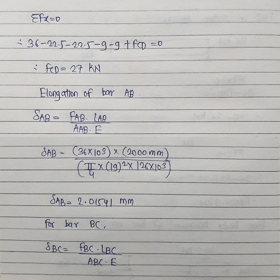
 Part A Determine the displacement of end A with respect to and D if the diameters of each segment are dam = 19 mm, dec = 26 mm, dcp = 14 mm. Take Ec= 126 GPa. the case contraction and positive Express your answer to three significant figures and include the appropriate units. Enter negative value value in the case of elongation. ? Value Units 225 The copper shaft is subjected to the axial loads shown in (Figure 1). Figure...
Question # 3 A shaft is subjected to the shown axial loads. The Modulus of Elasticity...
 Question # 3 A shaft is subjected to the shown axial loads. The Modulus of Elasticity is 18 x 10 psi. The diameters of rod sections are: das 0.75in,. dac-1 in., and de- 0.5 in. Determine the displacement of end A with respect to end D 80in.. ㅡ 150 in.. 100in. 5 kip 2 kip 6 kip A 5 kipB С 2kip l,
Problem 4.3 The composite shaft, consisting of aluminum, copper, and steel sections, is subjected to the...
 Problem 4.3 The composite shaft, consisting of aluminum, copper, and steel sections, is subjected to the loading shown. The cross-sectional areas of sections AB, BC and CD are A AB = 0.10 in?. ABC = 0.14 in?, and Acp = 0.06 in?, respectively. The modulus of elasticity for each section are shown in the figure. Neglect the size of the collars at B and C. (Figure 1) Figure 1 of 1 Aluminum El = 10(10) ksi Copper E = 18(10)...
The composite shaft, consisting of aluminum, copper, and steel sections, is subjected to the loading shown. The cross-se...
 The composite shaft, consisting of aluminum, copper, and steel
sections, is subjected to the loading shown. The cross-sectional
areas of sections AB, BC , and CD are
AAB = 0.08 in2 , ABC = 0.15
in2 , and ACD = 0.05 in2 ,
respectively. The modulus of elasticity for each section are shown
in the figure. Neglect the size of the collars at B and C.
(Figure 1)
Part A
Determine the normal stress in section AB.
Express your answer...
The composite shaft, consisting of aluminum, copper, and steel
sections, is subjected to the loading shown. The cross-sectional
areas of sections AB, BC , and CD are
AAB = 0.08 in2 , ABC = 0.15
in2 , and ACD = 0.05 in2 ,
respectively. The modulus of elasticity for each section are shown
in the figure. Neglect the size of the collars at B and C.
(Figure 1)
Part A
Determine the normal stress in section AB.
Express your answer...
A bar ABCD with varying cross section and subjected to axial loads is shown schematically in...
 A bar ABCD with varying cross section and subjected to axial loads is shown schematically in Figure Q3. Take modulus of elasticity of bar as 202 GPa. The length of each section L1 = 111 mm; L2 = 205 mm; and L3 = 451 mm. The cross sectional dimensions are as follows: Section 1 is square with side 49 mm, Section 2 is circular with diameter 79 mm and Section 3 is circular with diameter 32 mm. The forces are...
A circular shaft transmits power as shown with pulley loads. The shaft carries a torque, bending,...
 A circular shaft transmits power as shown with pulley loads. The shaft carries a torque, bending, shear and axial loads. Draw LVM diagram to find Mmax and Vmax. Show all loads (moments and forces) on the circular x-section of the shaft below. Use double arrows for moments. Compute shear and normal stresses and show them on the same section. Create stress elements for points A and B of the section. Combine the stresses and compute tmax (Tresca) and om (von...
Problem 2: A circular shaft transmits power as shown with pulley loads. The shaft carries a...
 Problem 2: A circular shaft transmits power as shown with pulley loads. The shaft carries a torque, bending, shear and axial loads. Draw LVM diagram to find Mmax and Vmax. Show all loads (moments and forces) on the circular x-section of the shaft below. Use double arrows for moments. Compute shear and normal stresses and show them on the same section. Create stress elements for points A and B of the section. Combine the stresses and compute Tmax (Tresca) and...
1. Refer to Problem 4-1 a. Determine the axial stress in the shaft. b. How much does the shaft shorten due to the t...
 1. Refer to Problem 4-1 a. Determine the axial stress in the shaft. b. How much does the shaft shorten due to the thrust from the propeller? c. If v 0.3, how much lateral strain would you expect? d. How much change would you expect in the diameter of the shaft? 4-1. The ship is pushed through the water using an A-36 steel propeller shaft that is 8 m long, measured from the propeller to the thrust bearing D at...
Problem 2: A circular shaft transmits power as shown with pulley loads. The shaft carries a...
 Problem 2: A circular shaft transmits power as shown with pulley loads. The shaft carries a torque, bending, shear and axial loads. Draw LVM diagram to find Mmax and Vmax. Show all loads (moments and forces) on the circular x-section of the shaft below. Use double arrows for moments. Compute shear and normal stresses and show them on the same section. Create stress elements for points A and B of the section. Combine the stresses and compute Cuau (Tresca) and...
 14-2. The copper shaft is subjected to the axial loads shown. Determine the displacement of end A with respect to end D if the diameters of each segment are dal = 0.75 in., dec=1 in., and dcp=0.5 in. Take Ecu = 18(109) ksi. -80 in.-- 5 kip 150 in.- +-100 in.--- 8 kip 2 kip 6 kip D 5 kip B C 2 kip Prob. 4-2
 Part A Determine the displacement of end A with respect to and D if the diameters of each segment are dam = 19 mm, dec = 26 mm, dcp = 14 mm. Take Ec= 126 GPa. the case contraction and positive Express your answer to three significant figures and include the appropriate units. Enter negative value value in the case of elongation. ? Value Units 225 The copper shaft is subjected to the axial loads shown in (Figure 1). Figure...
 Question # 3 A shaft is subjected to the shown axial loads. The Modulus of Elasticity is 18 x 10 psi. The diameters of rod sections are: das 0.75in,. dac-1 in., and de- 0.5 in. Determine the displacement of end A with respect to end D 80in.. ㅡ 150 in.. 100in. 5 kip 2 kip 6 kip A 5 kipB С 2kip l,
 Problem 4.3 The composite shaft, consisting of aluminum, copper, and steel sections, is subjected to the loading shown. The cross-sectional areas of sections AB, BC and CD are A AB = 0.10 in?. ABC = 0.14 in?, and Acp = 0.06 in?, respectively. The modulus of elasticity for each section are shown in the figure. Neglect the size of the collars at B and C. (Figure 1) Figure 1 of 1 Aluminum El = 10(10) ksi Copper E = 18(10)...
 The composite shaft, consisting of aluminum, copper, and steel
sections, is subjected to the loading shown. The cross-sectional
areas of sections AB, BC , and CD are
AAB = 0.08 in2 , ABC = 0.15
in2 , and ACD = 0.05 in2 ,
respectively. The modulus of elasticity for each section are shown
in the figure. Neglect the size of the collars at B and C.
(Figure 1)
Part A
Determine the normal stress in section AB.
Express your answer...
The composite shaft, consisting of aluminum, copper, and steel
sections, is subjected to the loading shown. The cross-sectional
areas of sections AB, BC , and CD are
AAB = 0.08 in2 , ABC = 0.15
in2 , and ACD = 0.05 in2 ,
respectively. The modulus of elasticity for each section are shown
in the figure. Neglect the size of the collars at B and C.
(Figure 1)
Part A
Determine the normal stress in section AB.
Express your answer...
 A bar ABCD with varying cross section and subjected to axial loads is shown schematically in Figure Q3. Take modulus of elasticity of bar as 202 GPa. The length of each section L1 = 111 mm; L2 = 205 mm; and L3 = 451 mm. The cross sectional dimensions are as follows: Section 1 is square with side 49 mm, Section 2 is circular with diameter 79 mm and Section 3 is circular with diameter 32 mm. The forces are...
 A circular shaft transmits power as shown with pulley loads. The shaft carries a torque, bending, shear and axial loads. Draw LVM diagram to find Mmax and Vmax. Show all loads (moments and forces) on the circular x-section of the shaft below. Use double arrows for moments. Compute shear and normal stresses and show them on the same section. Create stress elements for points A and B of the section. Combine the stresses and compute tmax (Tresca) and om (von...
 Problem 2: A circular shaft transmits power as shown with pulley loads. The shaft carries a torque, bending, shear and axial loads. Draw LVM diagram to find Mmax and Vmax. Show all loads (moments and forces) on the circular x-section of the shaft below. Use double arrows for moments. Compute shear and normal stresses and show them on the same section. Create stress elements for points A and B of the section. Combine the stresses and compute Tmax (Tresca) and...
 1. Refer to Problem 4-1 a. Determine the axial stress in the shaft. b. How much does the shaft shorten due to the thrust from the propeller? c. If v 0.3, how much lateral strain would you expect? d. How much change would you expect in the diameter of the shaft? 4-1. The ship is pushed through the water using an A-36 steel propeller shaft that is 8 m long, measured from the propeller to the thrust bearing D at...
 Problem 2: A circular shaft transmits power as shown with pulley loads. The shaft carries a torque, bending, shear and axial loads. Draw LVM diagram to find Mmax and Vmax. Show all loads (moments and forces) on the circular x-section of the shaft below. Use double arrows for moments. Compute shear and normal stresses and show them on the same section. Create stress elements for points A and B of the section. Combine the stresses and compute Cuau (Tresca) and...
Most questions answered within 3 hours.
-
On the Apollo 14 mission to the moon, astronaut Alan Shepard hit
a golf ball with...
asked 2 minutes from now -
Which of the following is not an ecological model used
to foster behavior change?
PRECEDE-PROCEED Model...
asked 1 minute ago -
What are John’s potential claims if he is terminated
this week?
John is a 54-year-old man...
asked 11 minutes ago -
A (8.5) cm tall object is placed at a distance of (14.2) cm from
a convex...
asked 19 minutes ago -
(2) For the following questions, consider a data set that
exhibits a normal distribution. Report the...
asked 20 minutes ago -
What exactly is an information system? How does it work" What
are its people organization,
...
asked 22 minutes ago -
The Food Marketing Institute shows that 17% of households spend
more than $100 per week on...
asked 31 minutes ago -
Go to NCBI BLAST search web page
1st search: GEKDLRRAKDINQEVYNF
2nd search: PTSQRLQLLEPFDK
3rd search: GEKDLRRAKDINQEVYNF...
asked 35 minutes ago -
Explain how each of the following three conditions could be a
red flag for a register...
asked 40 minutes ago -
In a two-way factorial ANOVA, the final F-ratio for
factor AxB is determined by dividing _____...
asked 1 hour ago -
Show your solutions for answer.
4. An aqueous solution contains 9.21 g of
K4Fe(CN)6 in a...
asked 40 minutes ago -
The random variable X has a uniform distribution with values
between 16 and 18. What is...
asked 50 minutes ago