
Homework Answers
(a)
 (b)
(b)


Add Answer to:
Problem 1. Use S-R flip-flops to design a 3-bit counter (C, B, A) with the repeating...
Problem 1. Use S-R flip-flops to design a 3-bit counter (C, B, A) with the repeating...
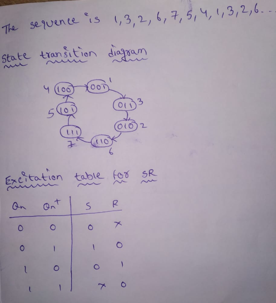
 Problem 1. Use S-R flip-flops to design a 3-bit counter (C, B, A) with the repeating binary counting sequence: 1, 3, 2, 6, 7, 5, 4. Show clearly the following: (a) The circuit's state table with the present-state entries in ascending order. 14 pts. Present State (t) Next State (t+1) Flip-flop Inputs с в А m C B A Sc Rc RE RA SB SA Required format of the state table in Problem 1(a). Show table grid lines and align...
Use S-R flip-flops to design a 3-bit counter (C, B, A) with the repeating binary counting...
 Use S-R flip-flops to design a 3-bit counter (C, B, A) with the repeating binary counting sequence: 1, 3, 2, 6, 7, 5, 4. Show clearly the following: (a) The circuit's state table with the present-state entries in ascending order. Present State (t) Next State (t+1) Flip-flop Inputs с B A m с B A Sc Rc SB RE SA RA Required format of the state table in Problem 1(a). Show table grid lines and align all entries per column....
Using S-R flip-flops, design a 3-bit counter (C,B,A) with the repeating binary counting sequence: 1, 3,...
Using S-R flip-flops, design a 3-bit counter (C,B,A) with the repeating binary counting sequence: 1, 3, 2, 6, 7, 5, 4. - Show the circuit's state table with the present-state entries in ascending order, which should have the present state (t), next state (t+1), and flip-flop inputs. - Find the flip-flop input equations for RC, RB, and RA in Product of Sums form.
Problem 2 Design a BCD counter that uses four(4) T flip-flops using the given table format...
 Problem 2 Design a BCD counter that uses four(4) T flip-flops using the given table format below. The output signal Y = 0 only during the counter transition from 1001 to 0000, otherwise, Y = 1 (for each valid input). Determine the following: (a) The circuit's state table 14 pts. Present State Next State Output Minterm Flip-Flop Inputs Q8 Q4 Q2 Q1 Q8Q4Q2 Y (m) TQ8 TQ4 TQ2 TQ1 Q1 Required format of the state table in Problem 2(a). Show...
Problem 2 Design a BCD counter that uses four(4) T flip-flops using the given table format...
 Problem 2 Design a BCD counter that uses four(4) T flip-flops using the given table format below. The output signal Y = 0 only during the counter transition from 1001 to 0000, otherwise, Y = 1 (for each valid input). Determine the following: (a) The circuit's state table Present State Next State Output Minterm Flip-Flop Inputs Q4 Q1 Q4 Q1 Y (m) TQ8 T04 TQ2 T01 14 pts. Required format of the state table in Problem 2(a). Show table grid...
Design a BCD counter that uses four(4) T flip-flops using the given table format below. The...
 Design a BCD counter that uses four(4) T flip-flops using the given table format below. The output signal Y = 0 only during the counter transition from 1001 to 0000, otherwise, Y = 1 (for each valid input). Determine the following: (a) The circuit's state table Present State Next State Output Minterm Flip-Flop Inputs Q. Q4 Q1 Q: Q4 Q2 Q1 Y (m) T24 T02 TQ1 T08 Required format of the state table in Problem 2(a). Show table grid lines...
Design a 5-bit binary counter using JK flip flops. Draw the flip-flop circuit diagram, the state...
Design a 5-bit binary counter using JK flip flops. Draw the flip-flop circuit diagram, the state graph, the timing diagram, the truth table (with clk pulse) and the state table (with present and next states).
Design a BCD counter with four T flip-flops. - The state table should have the present...
Design a BCD counter with four T flip-flops. - The state table should have the present state, next state, output, minterm, and flip-flop inputs. The output signal Y = 0 only during the counter transition from 1001 to 0000, otherwise, Y = 1 (for each valid input). - The input equation for TQ4, TQ2 and TQ1 in SOP. - The equation of the output signal Y in SOP.
Design a 4-bit binary up counter (like the following state diagram) using JK flip flops.
 Design a 4-bit binary up counter (like the following state diagram) using JK flip flops. State diagram. 0000 0001 11111 (a) Draw the state table with the input values for J K flip flops(b) Simplify the input equations by K map (c) Draw the logic diagram
3. A sequential circuit has 2 JK flip-flops A and B and one input x. The...
 3. A sequential circuit has 2 JK flip-flops A and B and one input x. The circuit is described by the following flip-flop input equations: (a) Derive the state equations A(t1) and B(t +1) by substituting the input equations for the J and K variables (b) Draw the state diagram of the circuit (c) Design an equivalent circuit using D flip flops, i.e. a sequential circuit that uses D flip flops to implement the state diagram you obtained in part...
 Problem 1. Use S-R flip-flops to design a 3-bit counter (C, B, A) with the repeating binary counting sequence: 1, 3, 2, 6, 7, 5, 4. Show clearly the following: (a) The circuit's state table with the present-state entries in ascending order. 14 pts. Present State (t) Next State (t+1) Flip-flop Inputs с в А m C B A Sc Rc RE RA SB SA Required format of the state table in Problem 1(a). Show table grid lines and align...
 Use S-R flip-flops to design a 3-bit counter (C, B, A) with the repeating binary counting sequence: 1, 3, 2, 6, 7, 5, 4. Show clearly the following: (a) The circuit's state table with the present-state entries in ascending order. Present State (t) Next State (t+1) Flip-flop Inputs с B A m с B A Sc Rc SB RE SA RA Required format of the state table in Problem 1(a). Show table grid lines and align all entries per column....
 Problem 2 Design a BCD counter that uses four(4) T flip-flops using the given table format below. The output signal Y = 0 only during the counter transition from 1001 to 0000, otherwise, Y = 1 (for each valid input). Determine the following: (a) The circuit's state table 14 pts. Present State Next State Output Minterm Flip-Flop Inputs Q8 Q4 Q2 Q1 Q8Q4Q2 Y (m) TQ8 TQ4 TQ2 TQ1 Q1 Required format of the state table in Problem 2(a). Show...
 Problem 2 Design a BCD counter that uses four(4) T flip-flops using the given table format below. The output signal Y = 0 only during the counter transition from 1001 to 0000, otherwise, Y = 1 (for each valid input). Determine the following: (a) The circuit's state table Present State Next State Output Minterm Flip-Flop Inputs Q4 Q1 Q4 Q1 Y (m) TQ8 T04 TQ2 T01 14 pts. Required format of the state table in Problem 2(a). Show table grid...
 Design a BCD counter that uses four(4) T flip-flops using the given table format below. The output signal Y = 0 only during the counter transition from 1001 to 0000, otherwise, Y = 1 (for each valid input). Determine the following: (a) The circuit's state table Present State Next State Output Minterm Flip-Flop Inputs Q. Q4 Q1 Q: Q4 Q2 Q1 Y (m) T24 T02 TQ1 T08 Required format of the state table in Problem 2(a). Show table grid lines...
 3. A sequential circuit has 2 JK flip-flops A and B and one input x. The circuit is described by the following flip-flop input equations: (a) Derive the state equations A(t1) and B(t +1) by substituting the input equations for the J and K variables (b) Draw the state diagram of the circuit (c) Design an equivalent circuit using D flip flops, i.e. a sequential circuit that uses D flip flops to implement the state diagram you obtained in part...
Most questions answered within 3 hours.
-
Accent Software faces the following conditions. All of these
support Accent’s use of a market-penetration pricing...
asked 16 minutes ago -
A mathematically inclined friend emails you the following
instructions: "Meet me in the cafeteria the first...
asked 19 minutes ago -
A monopoly sells in two countries . The demand curves in the two
countries are p1...
asked 1 hour ago -
A .15kg rubber ball is bounced off a wall. Before hitting the
wall, the ball moves...
asked 1 hour ago -
A manufacturing company preparing to build a new plant is
considering three potential locations for it....
asked 1 hour ago -
B. If compound Y has approximately the same values of solubility
in toluene as compound X,...
asked 2 hours ago -
Oscar Inc. has inventory in Japan valued at 39,051,000 Yen one
year ago. One year ago...
asked 2 hours ago -
If Canada suffered from "fundamental disequilibrium," and its
government choose not to devalue its currency, a...
asked 3 hours ago -
4. How many input & output Key Value Pairs are passed into,
and emitted out of...
asked 2 hours ago -
Why would your heart not function well if constructed of
skeletal muscle? What is the particular...
asked 3 hours ago -
Please respond to this essay question in full essay form for
Chemistry 1102 Organic and Biochemistry:...
asked 3 hours ago -
Determine the head loss and velocity of flow in a water supply main
of 15.0 cm...
asked 3 hours ago