
Homework Answers


Add Answer to:
Problem 2 Design a BCD counter that uses four(4) T flip-flops using the given table format...
Problem 2 Design a BCD counter that uses four(4) T flip-flops using the given table format...
 Problem 2 Design a BCD counter that uses four(4) T flip-flops using the given table format below. The output signal Y = 0 only during the counter transition from 1001 to 0000, otherwise, Y = 1 (for each valid input). Determine the following: (a) The circuit's state table Present State Next State Output Minterm Flip-Flop Inputs Q4 Q1 Q4 Q1 Y (m) TQ8 T04 TQ2 T01 14 pts. Required format of the state table in Problem 2(a). Show table grid...
Design a BCD counter that uses four(4) T flip-flops using the given table format below. The...
 Design a BCD counter that uses four(4) T flip-flops using the given table format below. The output signal Y = 0 only during the counter transition from 1001 to 0000, otherwise, Y = 1 (for each valid input). Determine the following: (a) The circuit's state table Present State Next State Output Minterm Flip-Flop Inputs Q. Q4 Q1 Q: Q4 Q2 Q1 Y (m) T24 T02 TQ1 T08 Required format of the state table in Problem 2(a). Show table grid lines...
Design a BCD counter with four T flip-flops. - The state table should have the present...
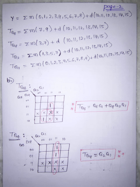
Design a BCD counter with four T flip-flops. - The state table should have the present state, next state, output, minterm, and flip-flop inputs. The output signal Y = 0 only during the counter transition from 1001 to 0000, otherwise, Y = 1 (for each valid input). - The input equation for TQ4, TQ2 and TQ1 in SOP. - The equation of the output signal Y in SOP.
Problem 1. Use S-R flip-flops to design a 3-bit counter (C, B, A) with the repeating...
 Problem 1. Use S-R flip-flops to design a 3-bit counter (C, B, A) with the repeating binary counting sequence: 1, 3, 2, 6, 7, 5, 4. Show clearly the following: (a) The circuit's state table with the present-state entries in ascending order. Present State (t) Next State (t+1) Flip-flop Inputs C B А m C B А Sc Rc SB RB SA RA 14 pts. Required format of the state table in Problem 1(a). Show table grid lines and align...
Problem 1. Use S-R flip-flops to design a 3-bit counter (C, B, A) with the repeating...
 Problem 1. Use S-R flip-flops to design a 3-bit counter (C, B, A) with the repeating binary counting sequence: 1, 3, 2, 6, 7, 5, 4. Show clearly the following: (a) The circuit's state table with the present-state entries in ascending order. 14 pts. Present State (t) Next State (t+1) Flip-flop Inputs с в А m C B A Sc Rc RE RA SB SA Required format of the state table in Problem 1(a). Show table grid lines and align...
Use S-R flip-flops to design a 3-bit counter (C, B, A) with the repeating binary counting...
 Use S-R flip-flops to design a 3-bit counter (C, B, A) with the repeating binary counting sequence: 1, 3, 2, 6, 7, 5, 4. Show clearly the following: (a) The circuit's state table with the present-state entries in ascending order. Present State (t) Next State (t+1) Flip-flop Inputs с B A m с B A Sc Rc SB RE SA RA Required format of the state table in Problem 1(a). Show table grid lines and align all entries per column....
Using S-R flip-flops, design a 3-bit counter (C,B,A) with the repeating binary counting sequence: 1, 3,...
Using S-R flip-flops, design a 3-bit counter (C,B,A) with the repeating binary counting sequence: 1, 3, 2, 6, 7, 5, 4. - Show the circuit's state table with the present-state entries in ascending order, which should have the present state (t), next state (t+1), and flip-flop inputs. - Find the flip-flop input equations for RC, RB, and RA in Product of Sums form.
(a) Design an asynchronous Binary Coded Decimal (BCD) count-up counter using JK flip-flops. Draw the counter circuit clearly showing the configuration of the JK flip-flops and the necessary logic gat...
 (a) Design an asynchronous Binary Coded Decimal (BCD) count-up counter using JK flip-flops. Draw the counter circuit clearly showing the configuration of the JK flip-flops and the necessary logic gate(s). Sketch the input and output waveforms of this counter (7 Marks) (b) The binary up/down counter for a cargo lift controller in a 7-storey building has an up-down (UID) control input and a buzzer output (B). The buzzer will sound B 1) when the lift is at level 1 or...
Please design a 4 bit synchrous counter (0-9 count) using t flip flops. Counter should reset...
Please design a 4 bit synchrous counter (0-9 count) using t flip flops. Counter should reset to 0 after 9. Kindly provide all steps including state table. I will be thankful to you.
Design a three-bit counter using D flip-flops that has the following characteristics: When the value of...
 Design a three-bit counter using D flip-flops that has the following characteristics: When the value of an input x is 0, the counter counts "down" in standard order. When the value of x is 1, the counter counts "up" in standard order a. First, complete the state table shown below Present State Next State Excitation 0 0 0 0 0 0 1 0 0 0 0 0 0 b. Next, derive the logic equations using the Karnaugh maps shown below...
 Problem 2 Design a BCD counter that uses four(4) T flip-flops using the given table format below. The output signal Y = 0 only during the counter transition from 1001 to 0000, otherwise, Y = 1 (for each valid input). Determine the following: (a) The circuit's state table Present State Next State Output Minterm Flip-Flop Inputs Q4 Q1 Q4 Q1 Y (m) TQ8 T04 TQ2 T01 14 pts. Required format of the state table in Problem 2(a). Show table grid...
 Design a BCD counter that uses four(4) T flip-flops using the given table format below. The output signal Y = 0 only during the counter transition from 1001 to 0000, otherwise, Y = 1 (for each valid input). Determine the following: (a) The circuit's state table Present State Next State Output Minterm Flip-Flop Inputs Q. Q4 Q1 Q: Q4 Q2 Q1 Y (m) T24 T02 TQ1 T08 Required format of the state table in Problem 2(a). Show table grid lines...
 Problem 1. Use S-R flip-flops to design a 3-bit counter (C, B, A) with the repeating binary counting sequence: 1, 3, 2, 6, 7, 5, 4. Show clearly the following: (a) The circuit's state table with the present-state entries in ascending order. Present State (t) Next State (t+1) Flip-flop Inputs C B А m C B А Sc Rc SB RB SA RA 14 pts. Required format of the state table in Problem 1(a). Show table grid lines and align...
 Problem 1. Use S-R flip-flops to design a 3-bit counter (C, B, A) with the repeating binary counting sequence: 1, 3, 2, 6, 7, 5, 4. Show clearly the following: (a) The circuit's state table with the present-state entries in ascending order. 14 pts. Present State (t) Next State (t+1) Flip-flop Inputs с в А m C B A Sc Rc RE RA SB SA Required format of the state table in Problem 1(a). Show table grid lines and align...
 Use S-R flip-flops to design a 3-bit counter (C, B, A) with the repeating binary counting sequence: 1, 3, 2, 6, 7, 5, 4. Show clearly the following: (a) The circuit's state table with the present-state entries in ascending order. Present State (t) Next State (t+1) Flip-flop Inputs с B A m с B A Sc Rc SB RE SA RA Required format of the state table in Problem 1(a). Show table grid lines and align all entries per column....
 (a) Design an asynchronous Binary Coded Decimal (BCD) count-up counter using JK flip-flops. Draw the counter circuit clearly showing the configuration of the JK flip-flops and the necessary logic gate(s). Sketch the input and output waveforms of this counter (7 Marks) (b) The binary up/down counter for a cargo lift controller in a 7-storey building has an up-down (UID) control input and a buzzer output (B). The buzzer will sound B 1) when the lift is at level 1 or...
 Design a three-bit counter using D flip-flops that has the following characteristics: When the value of an input x is 0, the counter counts "down" in standard order. When the value of x is 1, the counter counts "up" in standard order a. First, complete the state table shown below Present State Next State Excitation 0 0 0 0 0 0 1 0 0 0 0 0 0 b. Next, derive the logic equations using the Karnaugh maps shown below...
Most questions answered within 3 hours.
-
The Problem: The Case of the Harmonizing Vacations
Your CEO is exploring partnering with a European...
asked 41 minutes ago -
A chemical equation is balanced by adding coefficients in front
of some formulas so that the...
asked 40 minutes ago -
From the literature (reference your sources): What are the
lattice parameters of calcite and aragonite? Why...
asked 1 hour ago -
Your system is rejecting the question am asking which is
preceded by a case study. It...
asked 1 hour ago -
3. On January 2, 2000, Larry creates a trust with himself as
trustee. Larry as trustee...
asked 1 hour ago -
A member of the volleyball team spikes the ball. During this
process, she changes the velocity...
asked 1 hour ago -
Are adult gamers less likely to use a gaming console (Xbox,
PlayStation, Wii, etc...) than teen...
asked 2 hours ago -
The University of
Texas recently reported that 43% of college students aged 18-24
would spend their...
asked 2 hours ago -
The length of stay at a specific emergency department in
Phoenix, Arizona, in 2009 had a...
asked 1 hour ago -
. Please give the mechanism for this type of problem. Step by
Step
The toxin that...
asked 1 hour ago -
If you have a 1M stock solution and you want to dilute 1 :10
with water,...
asked 1 hour ago -
In a load instruction, the effective address is obtained by
A) Retriving the address from a...
asked 1 hour ago