
Homework Answers
Add Answer to:
C. The task is to create a complex counter that can count in binary or in...
Design a Verilog model that describes the following state diagram. (Test bench and simulation are not required) 1. 01 10 1- 10 10 01 01 10 or 01) 01 Design a Verilog model that describes a synchr...
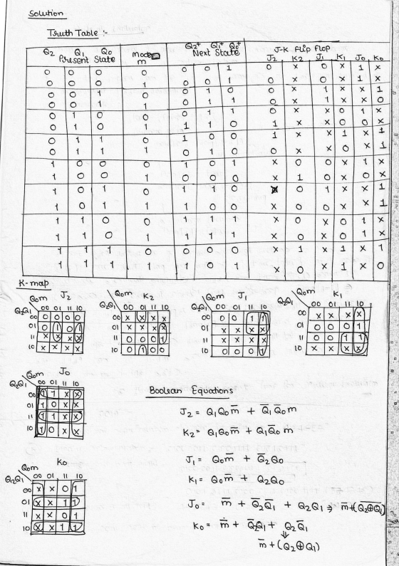
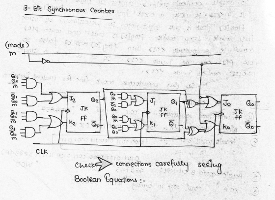
 Design a Verilog model that describes the following state diagram. (Test bench and simulation are not required) 1. 01 10 1- 10 10 01 01 10 or 01) 01 Design a Verilog model that describes a synchronous 3 bit counter. The counter has a counting mode control signal (M), when M-o, the counter counts up in the binary sequence, when M- 1, the counter advances through the Gray code sequence. (Test bench and simulation are required to verify the counter...
will give thumbs up need answer asap P3.94pts Implement a 3-bit synchronous gray code down-counter with...
 will give thumbs up need answer asap
P3.94pts Implement a 3-bit synchronous gray code down-counter with positive-edge-triggered D flip-flops using graphical symbols of D flip-flops and any logic gates. You can refer to the table below to understand the 3-bit gray code (The desired behavior is as follows: 000 100 101 111 - 110 - 010011001 → 000 → ...). Decimal 1 Gray code 000 001 011 010 110 111 101 100 5 6
will give thumbs up need answer asap
P3.94pts Implement a 3-bit synchronous gray code down-counter with positive-edge-triggered D flip-flops using graphical symbols of D flip-flops and any logic gates. You can refer to the table below to understand the 3-bit gray code (The desired behavior is as follows: 000 100 101 111 - 110 - 010011001 → 000 → ...). Decimal 1 Gray code 000 001 011 010 110 111 101 100 5 6
verilog code needed for the counter using the JK flip flop please include the testbench, thanks!...
 verilog code needed for the counter using the JK flip
flop
please include the testbench, thanks!
Successfully completing a System Verilog +80Pts. Implementation showing the full sequence of ABC readouts Pre-Laboratory Exercise: You are to design a counter that will count through a sequence either forward or reverse. You will have two control inputs: Direction, and Reset'. Sequence #2: 000 100 110 111 101001 → 011 010 → 000... {Gray code} When Direction=0 follow the order listed above. When Direction...
verilog code needed for the counter using the JK flip
flop
please include the testbench, thanks!
Successfully completing a System Verilog +80Pts. Implementation showing the full sequence of ABC readouts Pre-Laboratory Exercise: You are to design a counter that will count through a sequence either forward or reverse. You will have two control inputs: Direction, and Reset'. Sequence #2: 000 100 110 111 101001 → 011 010 → 000... {Gray code} When Direction=0 follow the order listed above. When Direction...
The first eight elements of binary and Gray code are given below: Binary | Gray 000...
The first eight elements of binary and Gray code are given below: Binary | Gray 000 | 000 001 | 001 010 | 011 011 | 010 100 | 110 101 | 111 110 | 101 111 | 100 Design a circuit that converts from binary to Gray code.
(4 pts) Write a behavioral Verilog module to implement a counter that counts in the following seq...
 Verilog! NOT VHDL Please
(4 pts) Write a behavioral Verilog module to implement a counter that counts in the following sequence: 000, 010, 100, 110, 001, 011, 101, 111, (repeat) 000, etc. Use a ROM and D flip-flops. Create a test bench for your counter design and run functional simulation in ModelSim.
(4 pts) Write a behavioral Verilog module to implement a counter that counts in the following sequence: 000, 010, 100, 110, 001, 011, 101, 111, (repeat) 000, etc....
Verilog! NOT VHDL Please
(4 pts) Write a behavioral Verilog module to implement a counter that counts in the following sequence: 000, 010, 100, 110, 001, 011, 101, 111, (repeat) 000, etc. Use a ROM and D flip-flops. Create a test bench for your counter design and run functional simulation in ModelSim.
(4 pts) Write a behavioral Verilog module to implement a counter that counts in the following sequence: 000, 010, 100, 110, 001, 011, 101, 111, (repeat) 000, etc....
Design a synchronous counter that has the following sequence: 000, 010, 101, 110 and repeat. The...
Design a synchronous counter that has the following sequence: 000, 010, 101, 110 and repeat. The undesired states 001, 011, 100 and 111 must always go to 000 on the next clock pulse.
Question 4 State Machines (25 marks) a. (5 marks) A 3-bit Gray code counter advances on...
 Question 4 State Machines (25 marks) a. (5 marks) A 3-bit Gray code counter advances on positive clock edges and generates outputs in the sequence: 000, 001, 011, 010, 110, 111, 101, 100. Draw the assigned state table for a state machine implementing this counter. b. (10 marks) For the Gray code counter in part a, derive (unoptimised) equations for the next state as a function of the current state. c. (10 marks) Consider the following sequence detector. In each...
Finite state machine (FSM) counter design: Gray codes have a useful property in that consecutive numbers differ in only a single bit position. Table 1 lists a 3-bit modulo 8 Gray code representing the...
 Finite state machine (FSM) counter design: Gray
codes have a useful property in that consecutive numbers differ in
only a single bit position. Table 1 lists a 3-bit modulo 8 Gray
code representing the numbers 0 to 7. Design a 3-bit modulo 8 Gray
code counter FSM.
a) First design and sketch a 3-bit modulo 8 Gray code counter
FSM with no inputs and three outputs, the 3-bit signal
Q2:0. (A modulo N counter counts from 0 to N −...
Finite state machine (FSM) counter design: Gray
codes have a useful property in that consecutive numbers differ in
only a single bit position. Table 1 lists a 3-bit modulo 8 Gray
code representing the numbers 0 to 7. Design a 3-bit modulo 8 Gray
code counter FSM.
a) First design and sketch a 3-bit modulo 8 Gray code counter
FSM with no inputs and three outputs, the 3-bit signal
Q2:0. (A modulo N counter counts from 0 to N −...
Design a Binary Counter with the repeating sequence of 100 - 110 - 111 - 011...
 Design a Binary Counter with the repeating sequence of 100 - 110 - 111 - 011 - 001 - 000 using T Flip-Flops. Find the input expressions of the T Flip-Flops by K-Map.
3. Design a counter with the following repeated binary sequence: 0,1,2,4,6. Use D flip-flop.
3. Design a counter with the following repeated binary sequence: 0,1,2,4,6. Use D flip-flop. 4. Design a counter to count with T flip-flops that goes through the following binary repeated sequence: 0,1,3,7,6,4. Find out the counter response towards the unused state. Illustrate the response with a state diagram. 5. Design a mod-7 counter (repeat binary sequence: 0,1,2,3,4,5,6) use JK flip-flop.
 Design a Verilog model that describes the following state diagram. (Test bench and simulation are not required) 1. 01 10 1- 10 10 01 01 10 or 01) 01 Design a Verilog model that describes a synchronous 3 bit counter. The counter has a counting mode control signal (M), when M-o, the counter counts up in the binary sequence, when M- 1, the counter advances through the Gray code sequence. (Test bench and simulation are required to verify the counter...
 will give thumbs up need answer asap
P3.94pts Implement a 3-bit synchronous gray code down-counter with positive-edge-triggered D flip-flops using graphical symbols of D flip-flops and any logic gates. You can refer to the table below to understand the 3-bit gray code (The desired behavior is as follows: 000 100 101 111 - 110 - 010011001 → 000 → ...). Decimal 1 Gray code 000 001 011 010 110 111 101 100 5 6
will give thumbs up need answer asap
P3.94pts Implement a 3-bit synchronous gray code down-counter with positive-edge-triggered D flip-flops using graphical symbols of D flip-flops and any logic gates. You can refer to the table below to understand the 3-bit gray code (The desired behavior is as follows: 000 100 101 111 - 110 - 010011001 → 000 → ...). Decimal 1 Gray code 000 001 011 010 110 111 101 100 5 6
 verilog code needed for the counter using the JK flip
flop
please include the testbench, thanks!
Successfully completing a System Verilog +80Pts. Implementation showing the full sequence of ABC readouts Pre-Laboratory Exercise: You are to design a counter that will count through a sequence either forward or reverse. You will have two control inputs: Direction, and Reset'. Sequence #2: 000 100 110 111 101001 → 011 010 → 000... {Gray code} When Direction=0 follow the order listed above. When Direction...
verilog code needed for the counter using the JK flip
flop
please include the testbench, thanks!
Successfully completing a System Verilog +80Pts. Implementation showing the full sequence of ABC readouts Pre-Laboratory Exercise: You are to design a counter that will count through a sequence either forward or reverse. You will have two control inputs: Direction, and Reset'. Sequence #2: 000 100 110 111 101001 → 011 010 → 000... {Gray code} When Direction=0 follow the order listed above. When Direction...
 Verilog! NOT VHDL Please
(4 pts) Write a behavioral Verilog module to implement a counter that counts in the following sequence: 000, 010, 100, 110, 001, 011, 101, 111, (repeat) 000, etc. Use a ROM and D flip-flops. Create a test bench for your counter design and run functional simulation in ModelSim.
(4 pts) Write a behavioral Verilog module to implement a counter that counts in the following sequence: 000, 010, 100, 110, 001, 011, 101, 111, (repeat) 000, etc....
Verilog! NOT VHDL Please
(4 pts) Write a behavioral Verilog module to implement a counter that counts in the following sequence: 000, 010, 100, 110, 001, 011, 101, 111, (repeat) 000, etc. Use a ROM and D flip-flops. Create a test bench for your counter design and run functional simulation in ModelSim.
(4 pts) Write a behavioral Verilog module to implement a counter that counts in the following sequence: 000, 010, 100, 110, 001, 011, 101, 111, (repeat) 000, etc....
 Question 4 State Machines (25 marks) a. (5 marks) A 3-bit Gray code counter advances on positive clock edges and generates outputs in the sequence: 000, 001, 011, 010, 110, 111, 101, 100. Draw the assigned state table for a state machine implementing this counter. b. (10 marks) For the Gray code counter in part a, derive (unoptimised) equations for the next state as a function of the current state. c. (10 marks) Consider the following sequence detector. In each...
 Finite state machine (FSM) counter design: Gray
codes have a useful property in that consecutive numbers differ in
only a single bit position. Table 1 lists a 3-bit modulo 8 Gray
code representing the numbers 0 to 7. Design a 3-bit modulo 8 Gray
code counter FSM.
a) First design and sketch a 3-bit modulo 8 Gray code counter
FSM with no inputs and three outputs, the 3-bit signal
Q2:0. (A modulo N counter counts from 0 to N −...
Finite state machine (FSM) counter design: Gray
codes have a useful property in that consecutive numbers differ in
only a single bit position. Table 1 lists a 3-bit modulo 8 Gray
code representing the numbers 0 to 7. Design a 3-bit modulo 8 Gray
code counter FSM.
a) First design and sketch a 3-bit modulo 8 Gray code counter
FSM with no inputs and three outputs, the 3-bit signal
Q2:0. (A modulo N counter counts from 0 to N −...
 Design a Binary Counter with the repeating sequence of 100 - 110 - 111 - 011 - 001 - 000 using T Flip-Flops. Find the input expressions of the T Flip-Flops by K-Map.
Most questions answered within 3 hours.
-
we
wish to estimate what percentage of adult residence in a certain
county are parents. out...
asked 14 minutes ago -
How do I calculate the kf for cyclohexane (pure
solvent)?
Also how to calculate the mass...
asked 13 minutes ago -
Alomar Co., a consolidated enterprise, conducted an impairment
review for each of its reporting units. In...
asked 14 minutes ago -
Write a public static method named
getMaxOf2Ints that takes in 2 int arguments and
returns the...
asked 38 minutes ago -
How will manager's behaviour change towards team members
as there would be a more cordial relationship...
asked 43 minutes ago -
You may need to use the appropriate appendix table or technology
to answer this question.
Consider...
asked 59 minutes ago -
The U.S. textile industry has had difficulty competing with
foreign imports in the past. If the...
asked 50 minutes ago -
A reaction that produces ammonia is shown below. How does the
catalyst used in the industrial...
asked 1 hour ago -
JAVA CODE Beginner. please use if, else if or switch
statements, but don't use arrays, please ...
asked 54 minutes ago -
On December 1, Year 1, Bradley Corporation incurs a 15-year
$200,000 mortgage liability in conjunction with...
asked 57 minutes ago -
- Perform Add round Key operation for the below
input =
A1
10
24
57
1F...
asked 58 minutes ago -
(IN JAVA)
Legend says that this problem was originated either by Buddhist
monks, Brahman priests, or...
asked 1 hour ago