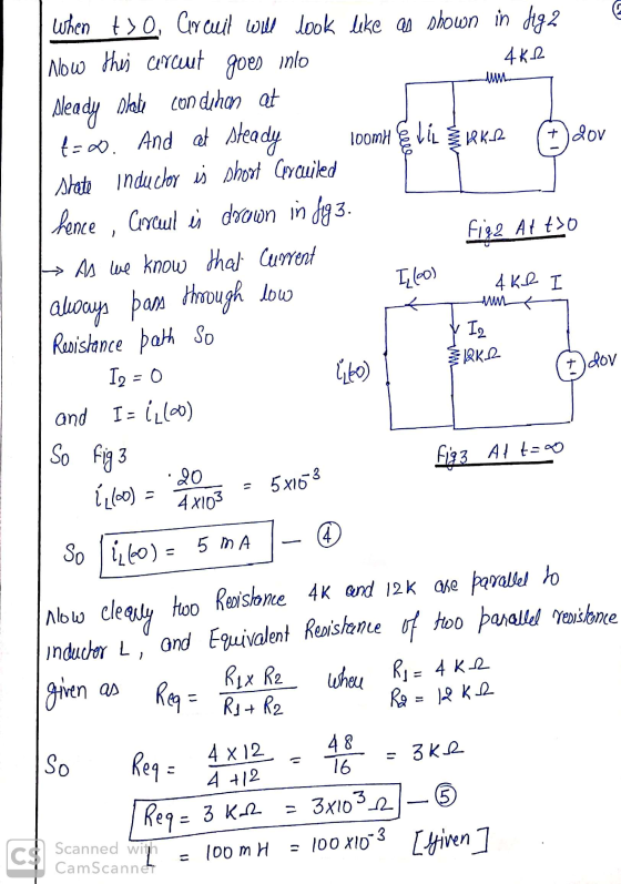
1. Use the step-by-step method on the circuit below to find the inductor current for all time.

2. Given the two complex numbers:

a) Express both numbers in rectangular, exponential, and phasor forms;
b) Find the sum, the difference, the product, and the quotient of the numbers.
3. Given the three sinusoids:

a) Find their corresponding phasors using a cosine reference;
b) Does x(t) lead or lag y(t), and by how much?
Homework Answers
![1 To Calculate Celrrent across inductor 1, we will use fiollowing Reg t L {(t) = [ [0+) - ibo)] e at formula +2.60) 1 w Where](http://img.homeworklib.com/questions/620ed940-08d2-11eb-a93e-0df4171912df.png?x-oss-process=image/resize,w_560)


Add Answer to:
1. Use the step-by-step method on the circuit below to find the
inductor current for all...
1. Use the step-by-step method on the circuit below to find the inductor current for all...
 1. Use the step-by-step method on the circuit below to find the inductor current for all time. 2 ΚΩ t = 0 4 ΚΩ + + 40V 12 ΚΩ 20V 100 mH
3. Given the three sinusoids: x(t)= 3cos(ot+45°) y(t)=2cos(at – 30°) z(t)= 4 sin(0t+30°) a) Find their...
 3. Given the three sinusoids: x(t)= 3cos(ot+45°) y(t)=2cos(at – 30°) z(t)= 4 sin(0t+30°) a) Find their corresponding phasors using a cosine reference; b) Does x(t) lead or lag y(t), and by how much?
1. Use the step-by-step method on the circuit below to find the inductor current for all...
 1. Use the step-by-step method on the circuit below to find the inductor current for all time. 2 ΚΩ t=0 4 ΚΩ + + 40 V 12 ΚΩ 20V 100 ml 3
(1) Use the step-by-step method to find Vo(t) for t>O in the circuit shown below. 4...
 (1) Use the step-by-step method to find Vo(t) for t>O in the circuit shown below. 4 ΚΩ 4 ΚΩ 200 μF ΑΛΛΑ 24 VB X, ο 34 ΚΩ 2 ΚΩ Bo(1)
4. (10.6) Find the output voltage (as a phasor) in the circuit below. j1 Ω 2Ω...
 4. (10.6) Find the output voltage (as a phasor) in the circuit below. j1 Ω 2Ω W 2020° 192 5/20 5. (10.42) Find the currents and voltages (as phasors) in the circuit below containing an ideal transformer. WW th ot 20 7602 20200 & 10 6. (10.43) Find the voltage (as phasor) in the circuit below containing an ideal transformer. 2:1 2:1 rün 402 W W of 22 2020 -120 lllll j622 lo 7. If Li - 30 mH, L2...
Part E - Use phasors to subtract one sinusoid from another sinusoid Suppose you want to...
 Part E - Use phasors to subtract one sinusoid from another sinusoid Suppose you want to find the difference of two sinusoidal currents, given as follows: ¿1(t) = 1; cos(wt+$1) and iz(t) = 12 cos(wt+$2). If you stay in the time domain, you will have to use trigonometric identities to perform the subtraction. But if you transform to the frequency domain, you can simply subtract the phasors I1 and 12 as complex numbers using y calculator. Make sure that all...
In the Circuit below find the phasor Vo of the output voltage vo-y when the input voltage us-f(t) Vs cos(ot) V. Plot 10log {lH(jo)l'3 function using the Bode Diagrams. Assume that all the Resista...
 In the Circuit below find the phasor Vo of the output voltage vo-y when the input voltage us-f(t) Vs cos(ot) V. Plot 10log {lH(jo)l'3 function using the Bode Diagrams. Assume that all the Resistance units are in ΚΩ and all the Capacitance units are in μF. 0.25 0.4
In the Circuit below find the phasor Vo of the output voltage vo-y when the input voltage us-f(t) Vs cos(ot) V. Plot 10log {lH(jo)l'3 function using the Bode Diagrams. Assume that all...
In the Circuit below find the phasor Vo of the output voltage vo-y when the input voltage us-f(t) Vs cos(ot) V. Plot 10log {lH(jo)l'3 function using the Bode Diagrams. Assume that all the Resistance units are in ΚΩ and all the Capacitance units are in μF. 0.25 0.4
In the Circuit below find the phasor Vo of the output voltage vo-y when the input voltage us-f(t) Vs cos(ot) V. Plot 10log {lH(jo)l'3 function using the Bode Diagrams. Assume that all...
Problem 2 (20 pts. Consider the following circuit. Use phasor method to find the following a....
 Problem 2 (20 pts. Consider the following circuit. Use phasor method to find the following a. i(t). b. iz(t). c. Average power absorbed by the controlled source. d. Average power absorbed by the independent source. e. Average power absorbed by the inductor. f. Average power absorbed by the capacitor. g. Average power absorbed by the resistor. 322 500 pF H4 10 cos 103t v ففف 4 mH I + 2i1
1. RL Circuits For the circuit in Figure 1, find the inductor voltage vit) if a)...
 1. RL Circuits For the circuit in Figure 1, find the inductor voltage vit) if a) v(t) is the step function: 0 Vfor t<0 and 10 V for t>0. What is the time constant in this case? b) vs(t) 15 cos(100 t). You may use either the direct time-domain method, or use (complex) phasor method. 52 102 5mH L(t) Figure 1 2. Impedance You are given six black boxes, labelled "1" to ", each with two terminals. You are told...
Circuit Analysis in the s-Domain 15.3. The initial voltage across the capacitor in the circuit shown in Figure P15.3 is v(0) 1 V, and the initial current through the inductor is i(0)0 mA Find th...
 Circuit Analysis in the s-Domain 15.3. The initial voltage across the capacitor in the circuit shown in Figure P15.3 is v(0) 1 V, and the initial current through the inductor is i(0)0 mA Find the voltage vo (t) across the capacitor for t 2 0 Figure P15.3 50 mH 1 kS2 V. Volt) T 0.1 μF The circuit in the s-domain is shown below. R2 Va 1k 0.05s 1/(sC)-1e7/s Vo R1 2k V (0-ys 5/s 1/s 1 format long; 2...
 1. Use the step-by-step method on the circuit below to find the inductor current for all time. 2 ΚΩ t = 0 4 ΚΩ + + 40V 12 ΚΩ 20V 100 mH
 3. Given the three sinusoids: x(t)= 3cos(ot+45°) y(t)=2cos(at – 30°) z(t)= 4 sin(0t+30°) a) Find their corresponding phasors using a cosine reference; b) Does x(t) lead or lag y(t), and by how much?
 1. Use the step-by-step method on the circuit below to find the inductor current for all time. 2 ΚΩ t=0 4 ΚΩ + + 40 V 12 ΚΩ 20V 100 ml 3
 (1) Use the step-by-step method to find Vo(t) for t>O in the circuit shown below. 4 ΚΩ 4 ΚΩ 200 μF ΑΛΛΑ 24 VB X, ο 34 ΚΩ 2 ΚΩ Bo(1)
 4. (10.6) Find the output voltage (as a phasor) in the circuit below. j1 Ω 2Ω W 2020° 192 5/20 5. (10.42) Find the currents and voltages (as phasors) in the circuit below containing an ideal transformer. WW th ot 20 7602 20200 & 10 6. (10.43) Find the voltage (as phasor) in the circuit below containing an ideal transformer. 2:1 2:1 rün 402 W W of 22 2020 -120 lllll j622 lo 7. If Li - 30 mH, L2...
 Part E - Use phasors to subtract one sinusoid from another sinusoid Suppose you want to find the difference of two sinusoidal currents, given as follows: ¿1(t) = 1; cos(wt+$1) and iz(t) = 12 cos(wt+$2). If you stay in the time domain, you will have to use trigonometric identities to perform the subtraction. But if you transform to the frequency domain, you can simply subtract the phasors I1 and 12 as complex numbers using y calculator. Make sure that all...
 In the Circuit below find the phasor Vo of the output voltage vo-y when the input voltage us-f(t) Vs cos(ot) V. Plot 10log {lH(jo)l'3 function using the Bode Diagrams. Assume that all the Resistance units are in ΚΩ and all the Capacitance units are in μF. 0.25 0.4
In the Circuit below find the phasor Vo of the output voltage vo-y when the input voltage us-f(t) Vs cos(ot) V. Plot 10log {lH(jo)l'3 function using the Bode Diagrams. Assume that all...
In the Circuit below find the phasor Vo of the output voltage vo-y when the input voltage us-f(t) Vs cos(ot) V. Plot 10log {lH(jo)l'3 function using the Bode Diagrams. Assume that all the Resistance units are in ΚΩ and all the Capacitance units are in μF. 0.25 0.4
In the Circuit below find the phasor Vo of the output voltage vo-y when the input voltage us-f(t) Vs cos(ot) V. Plot 10log {lH(jo)l'3 function using the Bode Diagrams. Assume that all...
 Problem 2 (20 pts. Consider the following circuit. Use phasor method to find the following a. i(t). b. iz(t). c. Average power absorbed by the controlled source. d. Average power absorbed by the independent source. e. Average power absorbed by the inductor. f. Average power absorbed by the capacitor. g. Average power absorbed by the resistor. 322 500 pF H4 10 cos 103t v ففف 4 mH I + 2i1
 1. RL Circuits For the circuit in Figure 1, find the inductor voltage vit) if a) v(t) is the step function: 0 Vfor t<0 and 10 V for t>0. What is the time constant in this case? b) vs(t) 15 cos(100 t). You may use either the direct time-domain method, or use (complex) phasor method. 52 102 5mH L(t) Figure 1 2. Impedance You are given six black boxes, labelled "1" to ", each with two terminals. You are told...
 Circuit Analysis in the s-Domain 15.3. The initial voltage across the capacitor in the circuit shown in Figure P15.3 is v(0) 1 V, and the initial current through the inductor is i(0)0 mA Find the voltage vo (t) across the capacitor for t 2 0 Figure P15.3 50 mH 1 kS2 V. Volt) T 0.1 μF The circuit in the s-domain is shown below. R2 Va 1k 0.05s 1/(sC)-1e7/s Vo R1 2k V (0-ys 5/s 1/s 1 format long; 2...
Most questions answered within 3 hours.
-
The extent to which assets are financed by borrowed funds and
other liabilities is indicated by:...
asked 41 minutes ago -
Explain in detail
Germany is the fifth largest economy
explain what goods and services Germany specializes...
asked 55 minutes ago -
The density of platinum is 21.45 g/mL. If a cube of platinum
with a mass of...
asked 1 hour ago -
Accounts Receivable
Sales
A/R Posting
Extended Sales Invoice
Packing Slip
Compare invoice to packing slip 2...
asked 1 hour ago -
Michaella, age 23, is a full-time law student and is claimed by
her parents as a...
asked 1 hour ago -
Why are polymers not typically casted into products?
asked 1 hour ago -
When rolling a die 129 times, what is the probability of rolling
a 6 no more...
asked 1 hour ago -
4. A call option currently sells for $7.75. It has a strike
price of $85 and...
asked 1 hour ago -
1.
You need to prepare 10.0 liters of an acid aqueous solution with a
pH of...
asked 1 hour ago -
Along an aggregate supply curve, if the level of output is less
than the natural level...
asked 1 hour ago -
By 2025, annual consumption in emerging markets will total $30
trillion and contribute more than ________...
asked 1 hour ago -
At what point does reformation cease to be a viable option for
those who are oppressed...
asked 1 hour ago