

Homework Answers


Add Answer to:
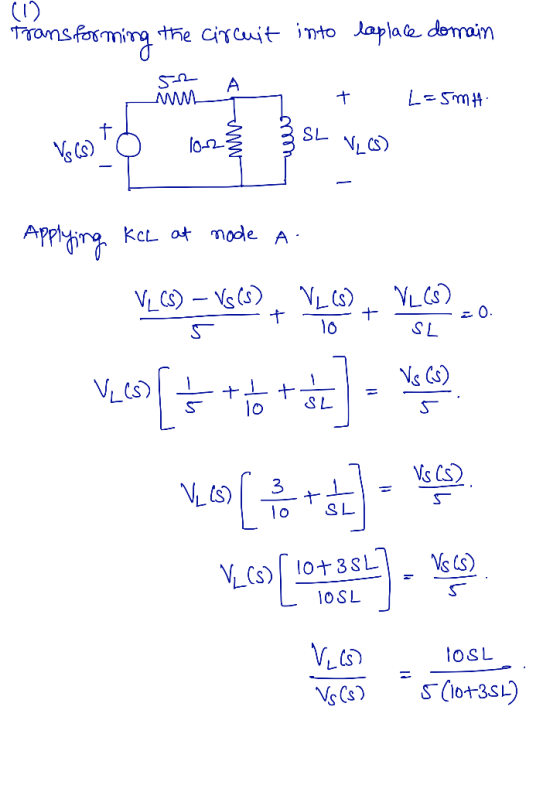
1. RL Circuits For the circuit in Figure 1, find the inductor voltage vit) if a)...
Question 1 For the circuit shown in figure 1; i. Find the transfer impedance function, H(s)...
 Question 1 For the circuit shown in figure 1; i. Find the transfer impedance function, H(s) = Vds(s) Find the poles and zeros for this transfer function and plot them on the s - Find the magnitude of the transfer function in decibels. [10] s-plane [8] ii [3] 2H 20 20 2 H Figure Question 2 The hybrid parameters (h-parameters) for the two -port network circuit in figure 2 are; 5 h=2 0.05 Find the equivalent impedance parameters (z-parameters) Find...
5. [RC Circuits] Consider the circuit shown in Figure 5 attached. As shown, the switch is...
 5. [RC Circuits] Consider the circuit shown in Figure 5 attached. As shown, the switch is in position "A" for t < 0, and the circuit has been at rest for a long time. At time t = 0, the switch opens and the capacitor starts to drain across the resistor. (a) When the switch is closed and there is only a direct current (DC) source, the capacitor acts like an open circuit. Find the constant voltage across the capacitor...
4. Consider the common-emitter amplifier of Figure 5. Draw the dc circuit and find ICQ. Draw the dc circuit and find IC...
 4. Consider the common-emitter amplifier of Figure 5. Draw the dc circuit and find ICQ. Draw the dc circuit and find ICQ. Find the value of Then, calculate values for Voltage gain Av, Open circuit voltage gain Avoc, input impedance Zin, current gain Ai, power gain G, and out- put impedance Zo. Assume operation in the frequency range for which influence of coupling and bypass capacitors can be ignored +15 V +15 V B 100 100 Ω 47ka Figure 5...
Problem 1: /10 A) For the RL circuit of Figure 1, the switch is closed at...
 Problem 1: /10 A) For the RL circuit of Figure 1, the switch is closed at t=0 (charging phase). Report the time constant of the circuit T1 , voltage V, and current i, at time t = t1/2 23 82H £292 3v 20 20 Fig. 1: EMILM B) At time t = t;/2 , the switch in the RL circuit of Figure 1 is opened (discharging phase); Report the time constant of the circuit ta , voltage V, and current...
4. Consider the common-emitter amplifier of Figure 5. Draw the dc circuit and find「CQ. Draw the...
 4. Consider the common-emitter amplifier of Figure 5. Draw the dc circuit and find「CQ. Draw the dc circuit and find ICQ. Find the value of r. Then, calculate values for Voltage gain Av, Open circuit voltage gain Avoc, input impedance Zin, current gain Ai, power gain G, and out- put impedance Zo. Assume operation in the frequency range for which influence of coupling and bypass capacitors can be ignored. +15 V +15 V s in 100Ω CE Figure 5
Please help with number 1. 1 SECTION - A Question 1 - DC Circuits and DC...
 Please help with number 1. 1
SECTION - A Question 1 - DC Circuits and DC Transients [25] After having been open for a very long time, the switch in the circuit shown in Figure 1 is closed at t= 0. Cat Find the currents 11, 12 and is immediately after the switch has been closed. 61 Find the equivalent resistance after the switch is closed and determine the time constant of the circuit. 0 Determine the mathematical expressions for...
Please help with number 1. 1
SECTION - A Question 1 - DC Circuits and DC Transients [25] After having been open for a very long time, the switch in the circuit shown in Figure 1 is closed at t= 0. Cat Find the currents 11, 12 and is immediately after the switch has been closed. 61 Find the equivalent resistance after the switch is closed and determine the time constant of the circuit. 0 Determine the mathematical expressions for...
6: In the circuit shown in Figure-6, input voltage of 15V de was switched ON at t-o. (a) Convert the circuit its Laplace equivalent at t >0, if ILO)-2A and vc (0)-6V. b) Find the capacitor voltage...
 6: In the circuit shown in Figure-6, input voltage of 15V de was switched ON at t-o. (a) Convert the circuit its Laplace equivalent at t >0, if ILO)-2A and vc (0)-6V. b) Find the capacitor voltage, Ve (s) in the frequency domain (c) Solve Ve (t) in the time domain. Switch L= 5H t-o 15V (0 ) = 2A V (o =6V 0.1F
6: In the circuit shown in Figure-6, input voltage of 15V de was switched ON at...
6: In the circuit shown in Figure-6, input voltage of 15V de was switched ON at t-o. (a) Convert the circuit its Laplace equivalent at t >0, if ILO)-2A and vc (0)-6V. b) Find the capacitor voltage, Ve (s) in the frequency domain (c) Solve Ve (t) in the time domain. Switch L= 5H t-o 15V (0 ) = 2A V (o =6V 0.1F
6: In the circuit shown in Figure-6, input voltage of 15V de was switched ON at...
Problem 1:(20 points) Consider the RL circuit in Figure 1. You may assume that the switch...
 Problem 1:(20 points) Consider the RL circuit in Figure 1. You may assume that the switch has been closed long enough for the voltages and currents to reach steady-state values. At timet 0 the switch is opened. 1 0 Rs Ri Figure 1: The switch in the RL circuit is opened at time t 0 1. (6 points) Find the voltage v(0-) and the current i(0) just before the switch is opened. 2. (6 points) Find the voltage v(0+) and...
This is a very interesting problem that i cant figure out. please answer the question clearly...
 This is a very interesting problem that i cant figure out.
please answer the question clearly and show all work.
Thanks!
A voltage source, in the circuit shown below, is short-circuited at its terminals by closing switch Si. At the time the switch is closed, the circuit has been in operation for a long time. Circuit values. Vs- 480 V Rs-1 S RI 10 ? R2 15? L1-2 mH L2-12 mH a) Find the initial value of the current through...
This is a very interesting problem that i cant figure out.
please answer the question clearly and show all work.
Thanks!
A voltage source, in the circuit shown below, is short-circuited at its terminals by closing switch Si. At the time the switch is closed, the circuit has been in operation for a long time. Circuit values. Vs- 480 V Rs-1 S RI 10 ? R2 15? L1-2 mH L2-12 mH a) Find the initial value of the current through...
1. RLC Circuits Revisited. The first example of a RLC circuit illustrates the use of circuit...
 1. RLC Circuits Revisited. The first example of a RLC circuit illustrates the use of circuit elements in the s domain to represent initial conditions and a forced response. Next an example of sinusoidal excitation will follow where the transient response and steady state response are combined into one response waveform.. Transient RLC Circuit with Initial Conditions. Consider the RLC circuit below in Figure 7.14 which has two DC sources (Vco and V) applied before and after a switch is...
 Question 1 For the circuit shown in figure 1; i. Find the transfer impedance function, H(s) = Vds(s) Find the poles and zeros for this transfer function and plot them on the s - Find the magnitude of the transfer function in decibels. [10] s-plane [8] ii [3] 2H 20 20 2 H Figure Question 2 The hybrid parameters (h-parameters) for the two -port network circuit in figure 2 are; 5 h=2 0.05 Find the equivalent impedance parameters (z-parameters) Find...
 5. [RC Circuits] Consider the circuit shown in Figure 5 attached. As shown, the switch is in position "A" for t < 0, and the circuit has been at rest for a long time. At time t = 0, the switch opens and the capacitor starts to drain across the resistor. (a) When the switch is closed and there is only a direct current (DC) source, the capacitor acts like an open circuit. Find the constant voltage across the capacitor...
 4. Consider the common-emitter amplifier of Figure 5. Draw the dc circuit and find ICQ. Draw the dc circuit and find ICQ. Find the value of Then, calculate values for Voltage gain Av, Open circuit voltage gain Avoc, input impedance Zin, current gain Ai, power gain G, and out- put impedance Zo. Assume operation in the frequency range for which influence of coupling and bypass capacitors can be ignored +15 V +15 V B 100 100 Ω 47ka Figure 5...
 Problem 1: /10 A) For the RL circuit of Figure 1, the switch is closed at t=0 (charging phase). Report the time constant of the circuit T1 , voltage V, and current i, at time t = t1/2 23 82H £292 3v 20 20 Fig. 1: EMILM B) At time t = t;/2 , the switch in the RL circuit of Figure 1 is opened (discharging phase); Report the time constant of the circuit ta , voltage V, and current...
 4. Consider the common-emitter amplifier of Figure 5. Draw the dc circuit and find「CQ. Draw the dc circuit and find ICQ. Find the value of r. Then, calculate values for Voltage gain Av, Open circuit voltage gain Avoc, input impedance Zin, current gain Ai, power gain G, and out- put impedance Zo. Assume operation in the frequency range for which influence of coupling and bypass capacitors can be ignored. +15 V +15 V s in 100Ω CE Figure 5
 Please help with number 1. 1
SECTION - A Question 1 - DC Circuits and DC Transients [25] After having been open for a very long time, the switch in the circuit shown in Figure 1 is closed at t= 0. Cat Find the currents 11, 12 and is immediately after the switch has been closed. 61 Find the equivalent resistance after the switch is closed and determine the time constant of the circuit. 0 Determine the mathematical expressions for...
Please help with number 1. 1
SECTION - A Question 1 - DC Circuits and DC Transients [25] After having been open for a very long time, the switch in the circuit shown in Figure 1 is closed at t= 0. Cat Find the currents 11, 12 and is immediately after the switch has been closed. 61 Find the equivalent resistance after the switch is closed and determine the time constant of the circuit. 0 Determine the mathematical expressions for...
 6: In the circuit shown in Figure-6, input voltage of 15V de was switched ON at t-o. (a) Convert the circuit its Laplace equivalent at t >0, if ILO)-2A and vc (0)-6V. b) Find the capacitor voltage, Ve (s) in the frequency domain (c) Solve Ve (t) in the time domain. Switch L= 5H t-o 15V (0 ) = 2A V (o =6V 0.1F
6: In the circuit shown in Figure-6, input voltage of 15V de was switched ON at...
6: In the circuit shown in Figure-6, input voltage of 15V de was switched ON at t-o. (a) Convert the circuit its Laplace equivalent at t >0, if ILO)-2A and vc (0)-6V. b) Find the capacitor voltage, Ve (s) in the frequency domain (c) Solve Ve (t) in the time domain. Switch L= 5H t-o 15V (0 ) = 2A V (o =6V 0.1F
6: In the circuit shown in Figure-6, input voltage of 15V de was switched ON at...
 Problem 1:(20 points) Consider the RL circuit in Figure 1. You may assume that the switch has been closed long enough for the voltages and currents to reach steady-state values. At timet 0 the switch is opened. 1 0 Rs Ri Figure 1: The switch in the RL circuit is opened at time t 0 1. (6 points) Find the voltage v(0-) and the current i(0) just before the switch is opened. 2. (6 points) Find the voltage v(0+) and...
 This is a very interesting problem that i cant figure out.
please answer the question clearly and show all work.
Thanks!
A voltage source, in the circuit shown below, is short-circuited at its terminals by closing switch Si. At the time the switch is closed, the circuit has been in operation for a long time. Circuit values. Vs- 480 V Rs-1 S RI 10 ? R2 15? L1-2 mH L2-12 mH a) Find the initial value of the current through...
This is a very interesting problem that i cant figure out.
please answer the question clearly and show all work.
Thanks!
A voltage source, in the circuit shown below, is short-circuited at its terminals by closing switch Si. At the time the switch is closed, the circuit has been in operation for a long time. Circuit values. Vs- 480 V Rs-1 S RI 10 ? R2 15? L1-2 mH L2-12 mH a) Find the initial value of the current through...
 1. RLC Circuits Revisited. The first example of a RLC circuit illustrates the use of circuit elements in the s domain to represent initial conditions and a forced response. Next an example of sinusoidal excitation will follow where the transient response and steady state response are combined into one response waveform.. Transient RLC Circuit with Initial Conditions. Consider the RLC circuit below in Figure 7.14 which has two DC sources (Vco and V) applied before and after a switch is...
Most questions answered within 3 hours.
-
Beginning Retained Earnings are $ 79 comma 000 $79,000; sales
are $ 31 comma 700 $31,700;...
asked 5 seconds from now -
Please explain/demonstrate how to use NLTK to test unigram,
bigram, and trigram character models on guessing...
asked 6 minutes ago -
what you feel is most important to you and why regarding your
typing skills?
asked 7 minutes ago -
Consider a play of the casino game `Quick Draw'. In this game, a
player pays $11...
asked 16 minutes ago -
How do the mechanical features of bone affect its roles as
repositories of phosphate and calcium,...
asked 20 minutes ago -
P agreed to buy 100 barrels of widget oil, which was stored in a
large tank...
asked 21 minutes ago -
The unstable isotope 40K is used for dating rock samples. Its
half-life is 1.28×10⁹y. How many...
asked 23 minutes ago -
Compare and contrast constructed-response items and
selected-response items.
Identify at least one (1) advantage and one...
asked 25 minutes ago -
A) Find the moment of inertia of a 2 meter long stick with a
mass of...
asked 24 minutes ago -
For the code below write a public static main() method
in class Student that:
- creates...
asked 26 minutes ago -
Please show all steps. Thank you
A 1.0-cm-diameter pipe widens to 2.0 cm, then narrows to...
asked 39 minutes ago -
The equilibrium constant for the following reaction Ag+(aq) +
2NH3(aq) Ag(NH3)2+(aq) is K = 1.7 ×...
asked 47 minutes ago