PLEASE SHOW ALL WORK AND TO FOLLOW ALL DIRECTIONS. PLEASE USE
PSPICE.
Homework Answers

Add Answer to:
PLEASE SHOW ALL WORK AND TO FOLLOW ALL DIRECTIONS. PLEASE USE
PSPICE.
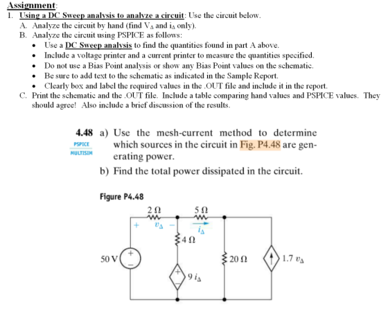
Assignment 1. Using a...
PLEASE SHOW ALL WORK AND TO FOLLOW DIRECTIONS. PLEASE USE PSPICE. STUDENT ID= 7220849 2. Using...
 PLEASE SHOW ALL WORK AND TO FOLLOW DIRECTIONS. PLEASE USE
PSPICE.
STUDENT ID= 7220849
2. Using a DC Sweep analysis to generate a table of values in the .OUT file: See Circuit 2 below: Let R1 through R6 equivalent to the digits 1 through 6 in your StudentID in k12 (use 10 k22 for a digit of 0). • For example, if your StudentID is 9870654 then R1 =9 kN, R2 =8 kN, R3 = 7kN, R4 = 10KN, R5...
PLEASE SHOW ALL WORK AND TO FOLLOW DIRECTIONS. PLEASE USE
PSPICE.
STUDENT ID= 7220849
2. Using a DC Sweep analysis to generate a table of values in the .OUT file: See Circuit 2 below: Let R1 through R6 equivalent to the digits 1 through 6 in your StudentID in k12 (use 10 k22 for a digit of 0). • For example, if your StudentID is 9870654 then R1 =9 kN, R2 =8 kN, R3 = 7kN, R4 = 10KN, R5...
PLEASE SHOW ALL WORK AND TO USE PSPICE AND FOLLOW ALL DIRECTIONS. STUDENT ID=378564 Assignment: 1....
 PLEASE SHOW ALL WORK AND TO USE PSPICE AND FOLLOW ALL
DIRECTIONS.
STUDENT ID=378564
Assignment: 1. For the Circuit 1 shown below: A. Analyze the circuit by hand as described in the textbook. B. Analyze the circuit using PSPICE as follows: Use a Bias Point analysis to find the quantities found in part A above. Be sure to add text to the schematic as indicated in the Sample Report. Adjust the placement of each value on the schematic so that...
PLEASE SHOW ALL WORK AND TO USE PSPICE AND FOLLOW ALL
DIRECTIONS.
STUDENT ID=378564
Assignment: 1. For the Circuit 1 shown below: A. Analyze the circuit by hand as described in the textbook. B. Analyze the circuit using PSPICE as follows: Use a Bias Point analysis to find the quantities found in part A above. Be sure to add text to the schematic as indicated in the Sample Report. Adjust the placement of each value on the schematic so that...
PLEASE SHOW ALL WORK AND TO FOLLOW DIRECTIONS. PLEASE USE PSPICE. STUDENT ID= 7220849 3. Using...
 PLEASE SHOW ALL WORK AND TO FOLLOW DIRECTIONS. PLEASE USE
PSPICE.
STUDENT ID= 7220849
3. Using a DC Sweep analysis to graph currents and voltages Let R1 through R4 equivalent to the digits 1 through 4 in your StudentID in k 2 (use 10 k12 for a digit of 0). • For example, if your StudentID is 9870654 then R1 =9 KS2, R2 =8 kN, R3 = 7k2 and R4 = 10k12 A. Analyze Circuit 3 by hand to determine...
PLEASE SHOW ALL WORK AND TO FOLLOW DIRECTIONS. PLEASE USE
PSPICE.
STUDENT ID= 7220849
3. Using a DC Sweep analysis to graph currents and voltages Let R1 through R4 equivalent to the digits 1 through 4 in your StudentID in k 2 (use 10 k12 for a digit of 0). • For example, if your StudentID is 9870654 then R1 =9 KS2, R2 =8 kN, R3 = 7k2 and R4 = 10k12 A. Analyze Circuit 3 by hand to determine...
Please show all work and to follow directions. Only answer Problem 14 14)(4 points) Analyze the...
 Please show all work and to follow directions. Only answer Problem
14
14)(4 points) Analyze the circuit in problem 9-12 using PSPICE as follows: Use a Bias Point analysis to find Ix, Iy, VA, VB and Vc in problem 12 above. Be sure to add text to the schematic as indicated in the Sample Report. Only show the result of Ix, ly, VA, VB and Ve on the schematic. Adjust the placement of each value on the schematic so that...
Please show all work and to follow directions. Only answer Problem
14
14)(4 points) Analyze the circuit in problem 9-12 using PSPICE as follows: Use a Bias Point analysis to find Ix, Iy, VA, VB and Vc in problem 12 above. Be sure to add text to the schematic as indicated in the Sample Report. Only show the result of Ix, ly, VA, VB and Ve on the schematic. Adjust the placement of each value on the schematic so that...
Consider the NPN transistor circuit below. Assume B=100 and Vee-on=0.7V. Calculate all three DC node voltages...
 Consider the NPN transistor circuit below. Assume B=100 and Vee-on=0.7V. Calculate all three DC node voltages and all five DC branch currents using hand-calculations and then verify in PSPICE using Bias Point Detail Analysis. In PSPICE, use the QBREAKN3 transistor and edit its model with BF=100. Please turn in both your hand-calculation solution and your PSPICE solution including your properly labeled PSPICE schematic. Note that write your hand-calculations right next to the corresponding PSPICE values on your PSPICE printout. Vcc=+15Volts...
SIMULATION EXERCISE # 3 Mesh Analysis" Given the following network: R1 V2 2k 5V V1 k R4 Vs volls 12 Tk 3k R3 R5 1. Simulate the above network using Pspice, Choose a value of Vs for the left...
 SIMULATION EXERCISE # 3 Mesh Analysis" Given the following network: R1 V2 2k 5V V1 k R4 Vs volls 12 Tk 3k R3 R5 1. Simulate the above network using Pspice, Choose a value of Vs for the left hand voltage source. Have values for the mesh currents I, and I2 appear on your schematic. By hand calculations use mesh analysis to determine the values of I1 and I2. Show your work
SIMULATION EXERCISE # 3 Mesh Analysis" Given the...
SIMULATION EXERCISE # 3 Mesh Analysis" Given the following network: R1 V2 2k 5V V1 k R4 Vs volls 12 Tk 3k R3 R5 1. Simulate the above network using Pspice, Choose a value of Vs for the left hand voltage source. Have values for the mesh currents I, and I2 appear on your schematic. By hand calculations use mesh analysis to determine the values of I1 and I2. Show your work
SIMULATION EXERCISE # 3 Mesh Analysis" Given the...
The circuit above is a Zener voltage regulator using D1N750 zener diode with Vz=4.7V: 1. Calculate...
 The circuit above is a Zener voltage regulator
using D1N750 zener diode with Vz=4.7V:
1. Calculate the minimum value of E in order to have the voltage
across RL regulated VL=Vz
2. Using Orcad PSpice schematics, simulate the
circuit using bias point and find Iz, IL, Is and Vz (the circuit
must have all voltages and currents values shown).
3. Using Orcad PSpice schematics, use DC sweep to
vary RL from 200 ohm to 1000 ohm and plot VL (for...
The circuit above is a Zener voltage regulator
using D1N750 zener diode with Vz=4.7V:
1. Calculate the minimum value of E in order to have the voltage
across RL regulated VL=Vz
2. Using Orcad PSpice schematics, simulate the
circuit using bias point and find Iz, IL, Is and Vz (the circuit
must have all voltages and currents values shown).
3. Using Orcad PSpice schematics, use DC sweep to
vary RL from 200 ohm to 1000 ohm and plot VL (for...
please do as soon as possible an use PSPICE I just need the pspice part please...
 please do as soon as possible an use PSPICE I just need
the pspice part
please use Pspice
use pspice to slove
Resistors 1.0kΩ, 1.2KΩ, 1.5ΚΩ, 1.8ΚΩ, 2.2kΩ, 2.7KΩ, 3.3kΩ, 3.9kΩ, 4.7kΩ, 5.6kΩ, 6.8ΚΩ, 8.2kΩ, 10kΩ, 12kΩ, 15kΩ, 18kΩ, 22kΩ, 27kg, 33kΩ, 30kΩ, 47ΚΩ, 56kΩ, 68kΩ, 82kΩ, 100kΩ. 120kΩ, 150kΩ, 180kΩ, 220kΩ, 270kΩ, 330kΩ, 39kΟΩ, 470kΩ, 560kΩ ** Put 60% 11:42 AM You Just now Part B. Non-Inverting Amplifier. Deliverables - PSpice schematic and graph 1. Draw the circuit for...
please do as soon as possible an use PSPICE I just need
the pspice part
please use Pspice
use pspice to slove
Resistors 1.0kΩ, 1.2KΩ, 1.5ΚΩ, 1.8ΚΩ, 2.2kΩ, 2.7KΩ, 3.3kΩ, 3.9kΩ, 4.7kΩ, 5.6kΩ, 6.8ΚΩ, 8.2kΩ, 10kΩ, 12kΩ, 15kΩ, 18kΩ, 22kΩ, 27kg, 33kΩ, 30kΩ, 47ΚΩ, 56kΩ, 68kΩ, 82kΩ, 100kΩ. 120kΩ, 150kΩ, 180kΩ, 220kΩ, 270kΩ, 330kΩ, 39kΟΩ, 470kΩ, 560kΩ ** Put 60% 11:42 AM You Just now Part B. Non-Inverting Amplifier. Deliverables - PSpice schematic and graph 1. Draw the circuit for...
Fall 2019 ECEN 206 Lab 4 Thevenin Equivalent Circuits Due First week of November Introduction: This...
 Fall 2019 ECEN 206 Lab 4 Thevenin Equivalent Circuits Due First week of November Introduction: This lab focuses on the Thevenin equivalent circuit and maximum power transfer theorems Complex circuits are often replaced with their Thevenin equivalent to simplify analysis. For example, in the analysis of large industrial power systems the Thevenin equivalent is used in short circuit studies. Maximum power transfer is also an important concept which allows the designer to determine an optimal design when power is a...
1) enin equivalent. one source. The purpose of this part is to find the Thévenin cquivalent...
 1) enin equivalent. one source. The purpose of this part is to find the Thévenin cquivalent of a circuit with one source by measuring find Vo and Isc a) Construct the circuit of Figure 7. Choose R1 = R2 R, 히0kΩ and set the value ofl.-6V using the 10V b) Measure the open-circuit voltage, V and the short-circuit current, I se, and thereby find Vy,and Rm Note: Do c) Using PSpice, create a simulation of the circuit. Attach a current...
 PLEASE SHOW ALL WORK AND TO FOLLOW DIRECTIONS. PLEASE USE
PSPICE.
STUDENT ID= 7220849
2. Using a DC Sweep analysis to generate a table of values in the .OUT file: See Circuit 2 below: Let R1 through R6 equivalent to the digits 1 through 6 in your StudentID in k12 (use 10 k22 for a digit of 0). • For example, if your StudentID is 9870654 then R1 =9 kN, R2 =8 kN, R3 = 7kN, R4 = 10KN, R5...
PLEASE SHOW ALL WORK AND TO FOLLOW DIRECTIONS. PLEASE USE
PSPICE.
STUDENT ID= 7220849
2. Using a DC Sweep analysis to generate a table of values in the .OUT file: See Circuit 2 below: Let R1 through R6 equivalent to the digits 1 through 6 in your StudentID in k12 (use 10 k22 for a digit of 0). • For example, if your StudentID is 9870654 then R1 =9 kN, R2 =8 kN, R3 = 7kN, R4 = 10KN, R5...
 PLEASE SHOW ALL WORK AND TO USE PSPICE AND FOLLOW ALL
DIRECTIONS.
STUDENT ID=378564
Assignment: 1. For the Circuit 1 shown below: A. Analyze the circuit by hand as described in the textbook. B. Analyze the circuit using PSPICE as follows: Use a Bias Point analysis to find the quantities found in part A above. Be sure to add text to the schematic as indicated in the Sample Report. Adjust the placement of each value on the schematic so that...
PLEASE SHOW ALL WORK AND TO USE PSPICE AND FOLLOW ALL
DIRECTIONS.
STUDENT ID=378564
Assignment: 1. For the Circuit 1 shown below: A. Analyze the circuit by hand as described in the textbook. B. Analyze the circuit using PSPICE as follows: Use a Bias Point analysis to find the quantities found in part A above. Be sure to add text to the schematic as indicated in the Sample Report. Adjust the placement of each value on the schematic so that...
 PLEASE SHOW ALL WORK AND TO FOLLOW DIRECTIONS. PLEASE USE
PSPICE.
STUDENT ID= 7220849
3. Using a DC Sweep analysis to graph currents and voltages Let R1 through R4 equivalent to the digits 1 through 4 in your StudentID in k 2 (use 10 k12 for a digit of 0). • For example, if your StudentID is 9870654 then R1 =9 KS2, R2 =8 kN, R3 = 7k2 and R4 = 10k12 A. Analyze Circuit 3 by hand to determine...
PLEASE SHOW ALL WORK AND TO FOLLOW DIRECTIONS. PLEASE USE
PSPICE.
STUDENT ID= 7220849
3. Using a DC Sweep analysis to graph currents and voltages Let R1 through R4 equivalent to the digits 1 through 4 in your StudentID in k 2 (use 10 k12 for a digit of 0). • For example, if your StudentID is 9870654 then R1 =9 KS2, R2 =8 kN, R3 = 7k2 and R4 = 10k12 A. Analyze Circuit 3 by hand to determine...
 Please show all work and to follow directions. Only answer Problem
14
14)(4 points) Analyze the circuit in problem 9-12 using PSPICE as follows: Use a Bias Point analysis to find Ix, Iy, VA, VB and Vc in problem 12 above. Be sure to add text to the schematic as indicated in the Sample Report. Only show the result of Ix, ly, VA, VB and Ve on the schematic. Adjust the placement of each value on the schematic so that...
Please show all work and to follow directions. Only answer Problem
14
14)(4 points) Analyze the circuit in problem 9-12 using PSPICE as follows: Use a Bias Point analysis to find Ix, Iy, VA, VB and Vc in problem 12 above. Be sure to add text to the schematic as indicated in the Sample Report. Only show the result of Ix, ly, VA, VB and Ve on the schematic. Adjust the placement of each value on the schematic so that...
 Consider the NPN transistor circuit below. Assume B=100 and Vee-on=0.7V. Calculate all three DC node voltages and all five DC branch currents using hand-calculations and then verify in PSPICE using Bias Point Detail Analysis. In PSPICE, use the QBREAKN3 transistor and edit its model with BF=100. Please turn in both your hand-calculation solution and your PSPICE solution including your properly labeled PSPICE schematic. Note that write your hand-calculations right next to the corresponding PSPICE values on your PSPICE printout. Vcc=+15Volts...
 SIMULATION EXERCISE # 3 Mesh Analysis" Given the following network: R1 V2 2k 5V V1 k R4 Vs volls 12 Tk 3k R3 R5 1. Simulate the above network using Pspice, Choose a value of Vs for the left hand voltage source. Have values for the mesh currents I, and I2 appear on your schematic. By hand calculations use mesh analysis to determine the values of I1 and I2. Show your work
SIMULATION EXERCISE # 3 Mesh Analysis" Given the...
SIMULATION EXERCISE # 3 Mesh Analysis" Given the following network: R1 V2 2k 5V V1 k R4 Vs volls 12 Tk 3k R3 R5 1. Simulate the above network using Pspice, Choose a value of Vs for the left hand voltage source. Have values for the mesh currents I, and I2 appear on your schematic. By hand calculations use mesh analysis to determine the values of I1 and I2. Show your work
SIMULATION EXERCISE # 3 Mesh Analysis" Given the...
 The circuit above is a Zener voltage regulator
using D1N750 zener diode with Vz=4.7V:
1. Calculate the minimum value of E in order to have the voltage
across RL regulated VL=Vz
2. Using Orcad PSpice schematics, simulate the
circuit using bias point and find Iz, IL, Is and Vz (the circuit
must have all voltages and currents values shown).
3. Using Orcad PSpice schematics, use DC sweep to
vary RL from 200 ohm to 1000 ohm and plot VL (for...
The circuit above is a Zener voltage regulator
using D1N750 zener diode with Vz=4.7V:
1. Calculate the minimum value of E in order to have the voltage
across RL regulated VL=Vz
2. Using Orcad PSpice schematics, simulate the
circuit using bias point and find Iz, IL, Is and Vz (the circuit
must have all voltages and currents values shown).
3. Using Orcad PSpice schematics, use DC sweep to
vary RL from 200 ohm to 1000 ohm and plot VL (for...
 please do as soon as possible an use PSPICE I just need
the pspice part
please use Pspice
use pspice to slove
Resistors 1.0kΩ, 1.2KΩ, 1.5ΚΩ, 1.8ΚΩ, 2.2kΩ, 2.7KΩ, 3.3kΩ, 3.9kΩ, 4.7kΩ, 5.6kΩ, 6.8ΚΩ, 8.2kΩ, 10kΩ, 12kΩ, 15kΩ, 18kΩ, 22kΩ, 27kg, 33kΩ, 30kΩ, 47ΚΩ, 56kΩ, 68kΩ, 82kΩ, 100kΩ. 120kΩ, 150kΩ, 180kΩ, 220kΩ, 270kΩ, 330kΩ, 39kΟΩ, 470kΩ, 560kΩ ** Put 60% 11:42 AM You Just now Part B. Non-Inverting Amplifier. Deliverables - PSpice schematic and graph 1. Draw the circuit for...
please do as soon as possible an use PSPICE I just need
the pspice part
please use Pspice
use pspice to slove
Resistors 1.0kΩ, 1.2KΩ, 1.5ΚΩ, 1.8ΚΩ, 2.2kΩ, 2.7KΩ, 3.3kΩ, 3.9kΩ, 4.7kΩ, 5.6kΩ, 6.8ΚΩ, 8.2kΩ, 10kΩ, 12kΩ, 15kΩ, 18kΩ, 22kΩ, 27kg, 33kΩ, 30kΩ, 47ΚΩ, 56kΩ, 68kΩ, 82kΩ, 100kΩ. 120kΩ, 150kΩ, 180kΩ, 220kΩ, 270kΩ, 330kΩ, 39kΟΩ, 470kΩ, 560kΩ ** Put 60% 11:42 AM You Just now Part B. Non-Inverting Amplifier. Deliverables - PSpice schematic and graph 1. Draw the circuit for...
 Fall 2019 ECEN 206 Lab 4 Thevenin Equivalent Circuits Due First week of November Introduction: This lab focuses on the Thevenin equivalent circuit and maximum power transfer theorems Complex circuits are often replaced with their Thevenin equivalent to simplify analysis. For example, in the analysis of large industrial power systems the Thevenin equivalent is used in short circuit studies. Maximum power transfer is also an important concept which allows the designer to determine an optimal design when power is a...
 1) enin equivalent. one source. The purpose of this part is to find the Thévenin cquivalent of a circuit with one source by measuring find Vo and Isc a) Construct the circuit of Figure 7. Choose R1 = R2 R, 히0kΩ and set the value ofl.-6V using the 10V b) Measure the open-circuit voltage, V and the short-circuit current, I se, and thereby find Vy,and Rm Note: Do c) Using PSpice, create a simulation of the circuit. Attach a current...
Most questions answered within 3 hours.
-
The manager at a car assembly plant believes that the mean
assembly time for a car...
asked 17 minutes ago -
Which of the following is true of electron capture?
A) It decreases the nuclide's mass number...
asked 1 hour ago -
Assuming an efficiency of 43.10%, calculate the actual yield of
magnesium nitrate formed from 114.9 g...
asked 2 hours ago -
The highly pathogenic bacterium Clostridium
perfringens causes gangrene, a disease that results in the
destruction of...
asked 4 hours ago -
In the context of situation analysis, which of the following is
a category for analysis in...
asked 4 hours ago -
In a study of the gas phase decomposition of sulfuryl chloride
at 600 K SO2Cl2(g)SO2(g) +...
asked 4 hours ago -
75 g of 2-propanol (C3H8O) and 25 g of pentane are mixed in a
200 mL...
asked 4 hours ago -
The 2800-turn coil in a dc motor has an area per turn of 1.1 ×
10-2...
asked 4 hours ago -
Draw a combinational logic circuit diagram with a symbol inside
the box for two I/P of...
asked 4 hours ago -
The cliché we use quite a lot in finance is: there is a need to
maximize...
asked 4 hours ago -
In class we discussed the addition of HCl to alpha pinene. Would
you expect one or...
asked 4 hours ago -
I'm trying to explain to my daughter to help her please help
me
I tagged the...
asked 4 hours ago