Grey code to Seven-Segment-LED design a circuit diagram for a Gray code–to–Binary converter that is conected...
Grey code to Seven-Segment-LED
design a circuit diagram for a Gray code–to–Binary converter that is conected to Seven-Segment-LED
Homework Answers


Add Answer to:
Grey code to Seven-Segment-LED
design a circuit diagram for a Gray code–to–Binary converter
that is conected...
4. Design a combinational circuit for a BCD to seven-segment code converter that will input a...
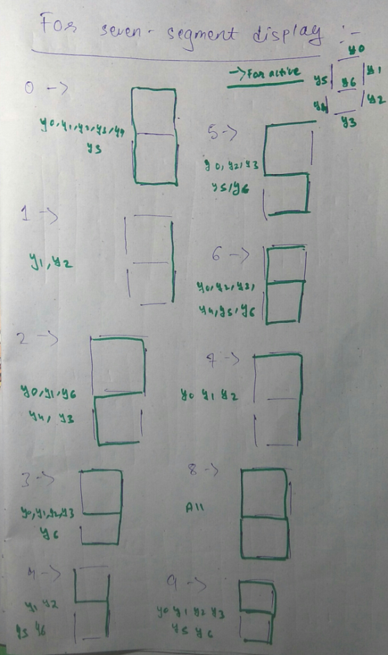
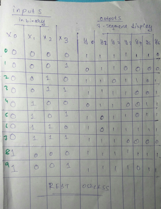
 4. Design a combinational circuit for a BCD to seven-segment code converter that will input a BCD number and output t on a seven segment common- anode display. The code converter will only display the number 8. Thoe converter wil turn the display OFF for all other valid BCD digits except digit 9 which will never occur. Draw a schematic. Show all steps clearly.
Logic Design Course assignment: Construct the truth table for 3 bit binary-to-Gray code converter. Use K-map...
Logic Design Course assignment: Construct the truth table for 3 bit binary-to-Gray code converter. Use K-map for simplification and draw the circuit for Binary-to-Gray code Converter using AND, OR and Not gates in logisim Simulator.
Design and implement a 4 bit- binary to gray code converter using CMOS transistors. ...
Design and implement a 4 bit- binary to gray code converter using CMOS transistors. (30 Marks) (Note: Students are expected to design the circuit with truth table, solve the output expression (by use of K Map or suitable circuit Reduction technique) and implement using CMOS transistors.)
QUESTION 2 (40 MARKS) Figure Q2 show Binary to Gray code converter block diagram. Based on...
 QUESTION 2 (40 MARKS) Figure Q2 show Binary to Gray code converter block diagram. Based on that figure, design: (a) Circuit using logic gates. Obtain the truth table and represent Yo, Y1, Y2 and Y3 in minimized SOP Boolean algebra term. Draw the circuit using logic gates (CO2:P03 - 20 Marks) (b) Circuit using 8 to 1 Multiplexer with A, B, C as a data selector. Obtain the truth table of each multiplexer. Draw the circuit using 8 to 1...
Design a 4-bit grey code adder. b) The adder has three components: two 4-bit grey-to-binary converters,...
Design a 4-bit grey code adder. b) The adder has three components: two 4-bit grey-to-binary converters, a 4-bit binary adder, and a 5-bit binary-to-grey code convertor. c) Model this design with SV as a combinational block. d) Write one test bench to verify the SV model. it will receive a grey input that then will be converter into binary to be added then out putting from binary back to gray
Design and implement a 4 bit- gray to binary code converter using CMOS transistors. (Note: Students are expected to design the circuit with truth table, solve the output expression (by...
Design and implement a 4 bit- gray to binary code converter using CMOS transistors. (Note: Students are expected to design the circuit with truth table, solve the output expression (by use of K Map or suitable circuit Reduction technique) and implement using CMOS transistors.)
Design an excess-3 code converter to drive a seven-segment indicator
 Design an excess-3 code converter to drive a seven-segment indicator. The four inputs to the converter circuit A, B, C, and Dasin Figure belowrepresent an excess-3 coded decimal digit. Assume that only input combinations representing the digits 0 through 9 can occur as inputs, so that the six unused combinations are don’tcares. Design your circuit using only two-, three-, and four-input NAND gates and inverters. Minimize the number of gates and invertersrequired.ThevariablesA,B,C,and Dwill be availablefromtoggle switches.
Exercise 5.6: Generic Binary-to-Gray Converter The regular binary code, which consists of code words ordered according...
 Exercise 5.6: Generic Binary-to-Gray Converter The regular binary code, which consists of code words ordered according to their increas ing unsigned decimal values, constitutes the most commonly used digital code. In some kind operation opcode 000 ya+b a(N-1:0) b(N-1:0) a(N-1:0) unsigned ya b 001 y(N- 1:0) Arithmetic Arithmetic 010 y-a+b ya+b+cin y(N:0) b(N-1:0 circuit circuit 011 cout cin cin 100 ya+b signed 101 ya b opcode(2:0) opcode(2:0) 110 y-a+b (a) (b) (c) 111 ya+b+cin Figure 5.14 applications, however, gray code...
Write VHDL code for a BCD-to-seven segment LED display converter with four inputs, h3-h0, representing a...
Write VHDL code for a BCD-to-seven segment LED display converter with four inputs, h3-h0, representing a single decimal digit, and a seven-bit output suitable for driving a seven segment LED display on the Altera DE1 board. Refer to the textbook on the sample codes. Do not just simply copy the codes. Please use negative logic for the seven segment LED display, i.e., use expression such as when "0000" =>leds<="0000001", as the DE1 board uses such logic for the LEDs.
Design an excess-3 code converter to drive a seven-segment indicator. The four inputs to the conv...
 can someone help me solve this please
Design an excess-3 code converter to drive a seven-segment indicator. The four inputs to the converter circuit represent an excess-3 coded decimal digit. Assume that only input combinations representing the digits 0 through 9 can occur as inputs, so that the six unused combinations are don't-cares. Implement the circuits using Decoder(s) (active low) and any necessary external gates and a separate solution using Multiplexer(S) and any necessary external gates Please specify the integrated...
can someone help me solve this please
Design an excess-3 code converter to drive a seven-segment indicator. The four inputs to the converter circuit represent an excess-3 coded decimal digit. Assume that only input combinations representing the digits 0 through 9 can occur as inputs, so that the six unused combinations are don't-cares. Implement the circuits using Decoder(s) (active low) and any necessary external gates and a separate solution using Multiplexer(S) and any necessary external gates Please specify the integrated...
 4. Design a combinational circuit for a BCD to seven-segment code converter that will input a BCD number and output t on a seven segment common- anode display. The code converter will only display the number 8. Thoe converter wil turn the display OFF for all other valid BCD digits except digit 9 which will never occur. Draw a schematic. Show all steps clearly.
 QUESTION 2 (40 MARKS) Figure Q2 show Binary to Gray code converter block diagram. Based on that figure, design: (a) Circuit using logic gates. Obtain the truth table and represent Yo, Y1, Y2 and Y3 in minimized SOP Boolean algebra term. Draw the circuit using logic gates (CO2:P03 - 20 Marks) (b) Circuit using 8 to 1 Multiplexer with A, B, C as a data selector. Obtain the truth table of each multiplexer. Draw the circuit using 8 to 1...
 Exercise 5.6: Generic Binary-to-Gray Converter The regular binary code, which consists of code words ordered according to their increas ing unsigned decimal values, constitutes the most commonly used digital code. In some kind operation opcode 000 ya+b a(N-1:0) b(N-1:0) a(N-1:0) unsigned ya b 001 y(N- 1:0) Arithmetic Arithmetic 010 y-a+b ya+b+cin y(N:0) b(N-1:0 circuit circuit 011 cout cin cin 100 ya+b signed 101 ya b opcode(2:0) opcode(2:0) 110 y-a+b (a) (b) (c) 111 ya+b+cin Figure 5.14 applications, however, gray code...
 can someone help me solve this please
Design an excess-3 code converter to drive a seven-segment indicator. The four inputs to the converter circuit represent an excess-3 coded decimal digit. Assume that only input combinations representing the digits 0 through 9 can occur as inputs, so that the six unused combinations are don't-cares. Implement the circuits using Decoder(s) (active low) and any necessary external gates and a separate solution using Multiplexer(S) and any necessary external gates Please specify the integrated...
can someone help me solve this please
Design an excess-3 code converter to drive a seven-segment indicator. The four inputs to the converter circuit represent an excess-3 coded decimal digit. Assume that only input combinations representing the digits 0 through 9 can occur as inputs, so that the six unused combinations are don't-cares. Implement the circuits using Decoder(s) (active low) and any necessary external gates and a separate solution using Multiplexer(S) and any necessary external gates Please specify the integrated...
Most questions answered within 3 hours.
-
The extent to which assets are financed by borrowed funds and
other liabilities is indicated by:...
asked 36 minutes ago -
Explain in detail
Germany is the fifth largest economy
explain what goods and services Germany specializes...
asked 50 minutes ago -
The density of platinum is 21.45 g/mL. If a cube of platinum
with a mass of...
asked 55 minutes ago -
Accounts Receivable
Sales
A/R Posting
Extended Sales Invoice
Packing Slip
Compare invoice to packing slip 2...
asked 58 minutes ago -
Michaella, age 23, is a full-time law student and is claimed by
her parents as a...
asked 59 minutes ago -
Why are polymers not typically casted into products?
asked 1 hour ago -
When rolling a die 129 times, what is the probability of rolling
a 6 no more...
asked 1 hour ago -
4. A call option currently sells for $7.75. It has a strike
price of $85 and...
asked 1 hour ago -
1.
You need to prepare 10.0 liters of an acid aqueous solution with a
pH of...
asked 1 hour ago -
Along an aggregate supply curve, if the level of output is less
than the natural level...
asked 1 hour ago -
By 2025, annual consumption in emerging markets will total $30
trillion and contribute more than ________...
asked 1 hour ago -
At what point does reformation cease to be a viable option for
those who are oppressed...
asked 1 hour ago