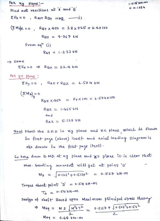
 1)Find the reaction force at point a and b. To find the tangent
force use this equation F^r =f^t * tan20
1)Find the reaction force at point a and b. To find the tangent
force use this equation F^r =f^t * tan20Homework Answers
Kindly check all steps and if still you are having any doubt, kindly let me know and if it is up to your satisfaction label, then kindly comment and like it. So that I will be that you are satisfied.


Add Answer to:
1)Find the reaction force at point a and b. To find the tangent
force use this...
can you please explain how to calculate the axial load for each gear and supporting load for each bearing? thank you! Task 1: A shaft is to be designed to support the spur pinion and helical gea...
 can you please explain how to calculate the axial load for
each gear and supporting load for each bearing? thank you!
Task 1: A shaft is to be designed to support the spur pinion and helical gear shown in the figure below on two bearings spaced 700 mm center-to-center. Bearing A is a cylindrical roller bearing and has to take only radial load; bearing B has to take the thrust load produced by the helical gear and its share of...
can you please explain how to calculate the axial load for
each gear and supporting load for each bearing? thank you!
Task 1: A shaft is to be designed to support the spur pinion and helical gear shown in the figure below on two bearings spaced 700 mm center-to-center. Bearing A is a cylindrical roller bearing and has to take only radial load; bearing B has to take the thrust load produced by the helical gear and its share of...
7-25 A shaft is to be designed to support the spur pinion and helical gear shown in the figure on two bearings spaced 700 mm center-to-center. Bearing A is a cylindrical roller and is to take onl...
 7-25 A shaft is to be designed to support the spur pinion and helical gear shown in the figure on two bearings spaced 700 mm center-to-center. Bearing A is a cylindrical roller and is to take only radial load; bearingB is to take the thrust load of 900 N produced by the helical gear and its share of the radial load. The bearing at B can be a bal bearing. The radial loads of both gears are in the same...
Is the factor of safety guarding against damaging distortion? What is the factor of safety guard-...
 is the factor of safety guarding against damaging distortion? What is the factor of safety guard- ing against a fatigue failure? If the shaft turns out to be unsatisfactory, what would you rec- ommend to correct the problem? A shaft is to be designed to support the spur pinion and helical gear shown in th two bearings spaced 28 in center-to-center. Bearing A is a cylindrical roller and is to take only radial load; bearing B is to take the...
2. Preliminary force analysis of the shaft in Problem 1 suggests that the reaction forces on the ...
 please solve #2
shaft from #1 above
2. Preliminary force analysis of the shaft in Problem 1 suggests that the reaction forces on the right side bearing are as follows: F-24 kN-5 = 3.35 kN, and = 1.5 kN. Size an angular contact bearing for the right side of the shaft for 10 kh of operation at 1400 RPM. Assume 92% reliability, ka-1. Is the large diameter of the shaft shoulder (52 mm) appropriately sized for the bearing you selected?...
please solve #2
shaft from #1 above
2. Preliminary force analysis of the shaft in Problem 1 suggests that the reaction forces on the right side bearing are as follows: F-24 kN-5 = 3.35 kN, and = 1.5 kN. Size an angular contact bearing for the right side of the shaft for 10 kh of operation at 1400 RPM. Assume 92% reliability, ka-1. Is the large diameter of the shaft shoulder (52 mm) appropriately sized for the bearing you selected?...
(5) The gear reduction unit shown has a gear that is press fit onto a cylindrical...
 (5) The gear reduction unit shown has a gear that is press fit onto a cylindrical sleeve that rotates around a stationary shaft. The helical gear transmits an axial thrust load of 300 Ibf as shown in the figure. Tangential and radial loads (not shown) are also transmitted through the gear, producing radial ground reaction forces at the bearings of 900 lbf for bearing A and 650 lbf for bearing B. The desired life for each bearing is 90 kh...
need solution step by step to question “H” (H) For the shaft of question (G) above, what are the X and Y forces on each of bearings B and E? Upward Y force on bearing E: Rey263 b Upward Y force...
 need solution step by step to question “H”
(H) For the shaft of question (G) above, what are the X and Y forces on each of bearings B and E? Upward Y force on bearing E: Rey263 b Upward Y force on bearing B: Rey1,838 b Outward X force on bearing E: Rex Outward X force on bearing B: Re1,569 b Answer Box 804 lb 36 REy Sum of Y moments around E = 0 Sum of Y Forces on...
need solution step by step to question “H”
(H) For the shaft of question (G) above, what are the X and Y forces on each of bearings B and E? Upward Y force on bearing E: Rey263 b Upward Y force on bearing B: Rey1,838 b Outward X force on bearing E: Rex Outward X force on bearing B: Re1,569 b Answer Box 804 lb 36 REy Sum of Y moments around E = 0 Sum of Y Forces on...
Figure below shows the load components acting on a helical gear mounted on a simply supported...
 Figure below shows the load components acting on a helical gear
mounted on a simply
supported shaft. Bearing B takes thrust. A flexible coupling for
transmitting
torque attaches to the right end of the shaft. The left end is
free.
1-Draw load, shear force, and bending moment diagrams for the
shaft, in both the horizontal and vertical planes.
2- Identify the most critically loaded shaft cross section, and
for this location determine the diameter theoretically required for
infinite life. Assume...
Figure below shows the load components acting on a helical gear
mounted on a simply
supported shaft. Bearing B takes thrust. A flexible coupling for
transmitting
torque attaches to the right end of the shaft. The left end is
free.
1-Draw load, shear force, and bending moment diagrams for the
shaft, in both the horizontal and vertical planes.
2- Identify the most critically loaded shaft cross section, and
for this location determine the diameter theoretically required for
infinite life. Assume...
Figure Q1 shows a gear train consists of four spur gears A, B, C and D to be designed for a specific mechanism. The power transmitted by gear A is 5 kW at rotational speed of 720 rpm counterclockwise direction. Number of teeth (N) for gears A,B,C and D ar
 Figure Q1 shows a gear train consists of four spur gears A, B, C and D to be designed for a specific
mechanism. The power transmitted by gear A is 5 kW at rotational speed of 720 rpm
counterclockwise direction. Number of teeth (N) for gears A,B,C and D are respectively 20, 50,
30 and 60. The module and pressure angle of the gears are respectively 4 mm and 20o
. Determine
followings:
(a) Tangential and radial forces between gears...
Figure Q1 shows a gear train consists of four spur gears A, B, C and D to be designed for a specific
mechanism. The power transmitted by gear A is 5 kW at rotational speed of 720 rpm
counterclockwise direction. Number of teeth (N) for gears A,B,C and D are respectively 20, 50,
30 and 60. The module and pressure angle of the gears are respectively 4 mm and 20o
. Determine
followings:
(a) Tangential and radial forces between gears...
Consider the simplified transmision sample problem shown in Figure 1 below. In this figure, matin...
 Consider the simplified transmision sample problem shown in Figure 1 below. In this figure, mating gears were shown to only exert tangential forces on each other. In reality, mating spur gear teeth will exert both tangential forces and radial forces2 due to the involute profile shape of the teeth (see Chapter 15, Figure 15.7). Let the diameters of gears B and D be 4.25 in while the diameters of gears A and C be 2.25 in. All other dimensions and...
Question 2 The shaft shown below is rotating at 650 rpm, and it receives 7.5 hp...
 Question 2 The shaft shown below is rotating at 650 rpm, and it receives 7.5 hp through a flexible coupling. The power is delivered to an adjacent shaft through a single helical gear B having a normal pressure angle of 20 degrees and a helix angle of 15 degrees. The pitch diameter for the gear is 4.141 inches (De) and the Tangential (Wu), radial (W) and axial/thrust (W) are shown below on the drawing. The shaft is to be made...
 can you please explain how to calculate the axial load for
each gear and supporting load for each bearing? thank you!
Task 1: A shaft is to be designed to support the spur pinion and helical gear shown in the figure below on two bearings spaced 700 mm center-to-center. Bearing A is a cylindrical roller bearing and has to take only radial load; bearing B has to take the thrust load produced by the helical gear and its share of...
can you please explain how to calculate the axial load for
each gear and supporting load for each bearing? thank you!
Task 1: A shaft is to be designed to support the spur pinion and helical gear shown in the figure below on two bearings spaced 700 mm center-to-center. Bearing A is a cylindrical roller bearing and has to take only radial load; bearing B has to take the thrust load produced by the helical gear and its share of...
 7-25 A shaft is to be designed to support the spur pinion and helical gear shown in the figure on two bearings spaced 700 mm center-to-center. Bearing A is a cylindrical roller and is to take only radial load; bearingB is to take the thrust load of 900 N produced by the helical gear and its share of the radial load. The bearing at B can be a bal bearing. The radial loads of both gears are in the same...
 is the factor of safety guarding against damaging distortion? What is the factor of safety guard- ing against a fatigue failure? If the shaft turns out to be unsatisfactory, what would you rec- ommend to correct the problem? A shaft is to be designed to support the spur pinion and helical gear shown in th two bearings spaced 28 in center-to-center. Bearing A is a cylindrical roller and is to take only radial load; bearing B is to take the...
 please solve #2
shaft from #1 above
2. Preliminary force analysis of the shaft in Problem 1 suggests that the reaction forces on the right side bearing are as follows: F-24 kN-5 = 3.35 kN, and = 1.5 kN. Size an angular contact bearing for the right side of the shaft for 10 kh of operation at 1400 RPM. Assume 92% reliability, ka-1. Is the large diameter of the shaft shoulder (52 mm) appropriately sized for the bearing you selected?...
please solve #2
shaft from #1 above
2. Preliminary force analysis of the shaft in Problem 1 suggests that the reaction forces on the right side bearing are as follows: F-24 kN-5 = 3.35 kN, and = 1.5 kN. Size an angular contact bearing for the right side of the shaft for 10 kh of operation at 1400 RPM. Assume 92% reliability, ka-1. Is the large diameter of the shaft shoulder (52 mm) appropriately sized for the bearing you selected?...
 (5) The gear reduction unit shown has a gear that is press fit onto a cylindrical sleeve that rotates around a stationary shaft. The helical gear transmits an axial thrust load of 300 Ibf as shown in the figure. Tangential and radial loads (not shown) are also transmitted through the gear, producing radial ground reaction forces at the bearings of 900 lbf for bearing A and 650 lbf for bearing B. The desired life for each bearing is 90 kh...
 need solution step by step to question “H”
(H) For the shaft of question (G) above, what are the X and Y forces on each of bearings B and E? Upward Y force on bearing E: Rey263 b Upward Y force on bearing B: Rey1,838 b Outward X force on bearing E: Rex Outward X force on bearing B: Re1,569 b Answer Box 804 lb 36 REy Sum of Y moments around E = 0 Sum of Y Forces on...
need solution step by step to question “H”
(H) For the shaft of question (G) above, what are the X and Y forces on each of bearings B and E? Upward Y force on bearing E: Rey263 b Upward Y force on bearing B: Rey1,838 b Outward X force on bearing E: Rex Outward X force on bearing B: Re1,569 b Answer Box 804 lb 36 REy Sum of Y moments around E = 0 Sum of Y Forces on...
 Figure below shows the load components acting on a helical gear
mounted on a simply
supported shaft. Bearing B takes thrust. A flexible coupling for
transmitting
torque attaches to the right end of the shaft. The left end is
free.
1-Draw load, shear force, and bending moment diagrams for the
shaft, in both the horizontal and vertical planes.
2- Identify the most critically loaded shaft cross section, and
for this location determine the diameter theoretically required for
infinite life. Assume...
Figure below shows the load components acting on a helical gear
mounted on a simply
supported shaft. Bearing B takes thrust. A flexible coupling for
transmitting
torque attaches to the right end of the shaft. The left end is
free.
1-Draw load, shear force, and bending moment diagrams for the
shaft, in both the horizontal and vertical planes.
2- Identify the most critically loaded shaft cross section, and
for this location determine the diameter theoretically required for
infinite life. Assume...
 Consider the simplified transmision sample problem shown in Figure 1 below. In this figure, mating gears were shown to only exert tangential forces on each other. In reality, mating spur gear teeth will exert both tangential forces and radial forces2 due to the involute profile shape of the teeth (see Chapter 15, Figure 15.7). Let the diameters of gears B and D be 4.25 in while the diameters of gears A and C be 2.25 in. All other dimensions and...
 Question 2 The shaft shown below is rotating at 650 rpm, and it receives 7.5 hp through a flexible coupling. The power is delivered to an adjacent shaft through a single helical gear B having a normal pressure angle of 20 degrees and a helix angle of 15 degrees. The pitch diameter for the gear is 4.141 inches (De) and the Tangential (Wu), radial (W) and axial/thrust (W) are shown below on the drawing. The shaft is to be made...
Most questions answered within 3 hours.
-
You place a block of
ice (mass of 3 kg) into a test chamber filled with...
asked 3 minutes ago -
Write which type of radiation (alpha, beta, gamma, or positron)
matches the following
descriptors. Each type...
asked 5 minutes ago -
Describe and draw the mechanism for the formation of the
Grignard reagent with 2-bromopropane as the...
asked 6 minutes ago -
Work out a care plan for Rex to help her better manage
her medical conditions. Provide...
asked 16 minutes ago -
The historical returns on a balanced portfolio have had an
average return of 11% and a...
asked 21 minutes ago -
Sulfuric acid (250.0mL) is titrated with 176.5 mL 2.4 M NaOH to
an equivalence point (the...
asked 33 minutes ago -
The quality control manager of a cookie company is inspecting a
batch of chocolate-chip cookies that...
asked 34 minutes ago -
How can we identify what the horizontal force is when looking at
a merry go round?...
asked 1 hour ago -
While Dime Community Bank is based in Brooklyn; management has
decided to focus its lending activity...
asked 1 hour ago -
1) Earnings functions, whereby the log of earnings is regressed
on years of education, years of...
asked 1 hour ago -
Bruno Corporation is involved in the business of injection
molding of plastics. It is considering the...
asked 1 hour ago -
What would be the vapor pressure of water at 96°C above a
solution made by dissolving...
asked 1 hour ago