
Homework Answers
Add Answer to:
(5) The gear reduction unit shown has a gear that is press fit onto a cylindrical...
7-25 A shaft is to be designed to support the spur pinion and helical gear shown in the figure on two bearings spaced 700 mm center-to-center. Bearing A is a cylindrical roller and is to take onl...
 7-25 A shaft is to be designed to support the spur pinion and helical gear shown in the figure on two bearings spaced 700 mm center-to-center. Bearing A is a cylindrical roller and is to take only radial load; bearingB is to take the thrust load of 900 N produced by the helical gear and its share of the radial load. The bearing at B can be a bal bearing. The radial loads of both gears are in the same...
Is the factor of safety guarding against damaging distortion? What is the factor of safety guard-...
 is the factor of safety guarding against damaging distortion? What is the factor of safety guard- ing against a fatigue failure? If the shaft turns out to be unsatisfactory, what would you rec- ommend to correct the problem? A shaft is to be designed to support the spur pinion and helical gear shown in th two bearings spaced 28 in center-to-center. Bearing A is a cylindrical roller and is to take only radial load; bearing B is to take the...
can you please explain how to calculate the axial load for each gear and supporting load for each bearing? thank you! Task 1: A shaft is to be designed to support the spur pinion and helical gea...
 can you please explain how to calculate the axial load for
each gear and supporting load for each bearing? thank you!
Task 1: A shaft is to be designed to support the spur pinion and helical gear shown in the figure below on two bearings spaced 700 mm center-to-center. Bearing A is a cylindrical roller bearing and has to take only radial load; bearing B has to take the thrust load produced by the helical gear and its share of...
can you please explain how to calculate the axial load for
each gear and supporting load for each bearing? thank you!
Task 1: A shaft is to be designed to support the spur pinion and helical gear shown in the figure below on two bearings spaced 700 mm center-to-center. Bearing A is a cylindrical roller bearing and has to take only radial load; bearing B has to take the thrust load produced by the helical gear and its share of...
A straight-bevel gear mesh is utilized to transform the rotation about a horizontal shaft of a...
 A straight-bevel gear mesh is utilized to transform the rotation
about a horizontal shaft of a motor-driven pinion into rotation of
an output gear about a vertical shaft as shown in Fig. 1. The
pressure angle f = 20°. The pinion shaft rotates at 900 rpm.
a. Both pinion and gear are Grade 2 steel through-hardened at
250 Brinell and are uncrowned. The quality number is 9 and the
desired life is 30,000 hours with a 0.999 reliability. For a...
A straight-bevel gear mesh is utilized to transform the rotation
about a horizontal shaft of a motor-driven pinion into rotation of
an output gear about a vertical shaft as shown in Fig. 1. The
pressure angle f = 20°. The pinion shaft rotates at 900 rpm.
a. Both pinion and gear are Grade 2 steel through-hardened at
250 Brinell and are uncrowned. The quality number is 9 and the
desired life is 30,000 hours with a 0.999 reliability. For a...
QUESTION 10 The shaft shown in the figure is driven by a gear at the right...
 QUESTION 10 The shaft shown in the figure is driven by a gear at the right keyway, drives a fan at the left keyway, and is supported by two deep-groove ball bearings at locations A and B. The shaft is made from AISI 1045 cold-drawn steel. At steady-state speed, the gear transmits a radial load of 300 lbf and a tangential load of 700 lbf at a pitch diameter of 8 in. Assume that the weight and axial load of...
The shaft shown in the figure is driven by a gear at the right keyway, drives...
 The shaft shown in the figure is driven by a gear at the right keyway, drives a fan at the left keyway, and is supported by two deep-groove ball bearings at locations A and B. The shaft is made from AISI 1045 cold-drawn steel. At steady-state speed, the gear transmits a radial load of 300 lbf and a tangential load of 700 lbf at a pitch diameter of 8 in. Assume that the weight and axial load of the fan...
Question 2 The shaft shown below is rotating at 650 rpm, and it receives 7.5 hp...
 Question 2 The shaft shown below is rotating at 650 rpm, and it receives 7.5 hp through a flexible coupling. The power is delivered to an adjacent shaft through a single helical gear B having a normal pressure angle of 20 degrees and a helix angle of 15 degrees. The pitch diameter for the gear is 4.141 inches (De) and the Tangential (Wu), radial (W) and axial/thrust (W) are shown below on the drawing. The shaft is to be made...
Figure below shows the load components acting on a helical gear mounted on a simply supported...
 Figure below shows the load components acting on a helical gear
mounted on a simply
supported shaft. Bearing B takes thrust. A flexible coupling for
transmitting
torque attaches to the right end of the shaft. The left end is
free.
1-Draw load, shear force, and bending moment diagrams for the
shaft, in both the horizontal and vertical planes.
2- Identify the most critically loaded shaft cross section, and
for this location determine the diameter theoretically required for
infinite life. Assume...
Figure below shows the load components acting on a helical gear
mounted on a simply
supported shaft. Bearing B takes thrust. A flexible coupling for
transmitting
torque attaches to the right end of the shaft. The left end is
free.
1-Draw load, shear force, and bending moment diagrams for the
shaft, in both the horizontal and vertical planes.
2- Identify the most critically loaded shaft cross section, and
for this location determine the diameter theoretically required for
infinite life. Assume...
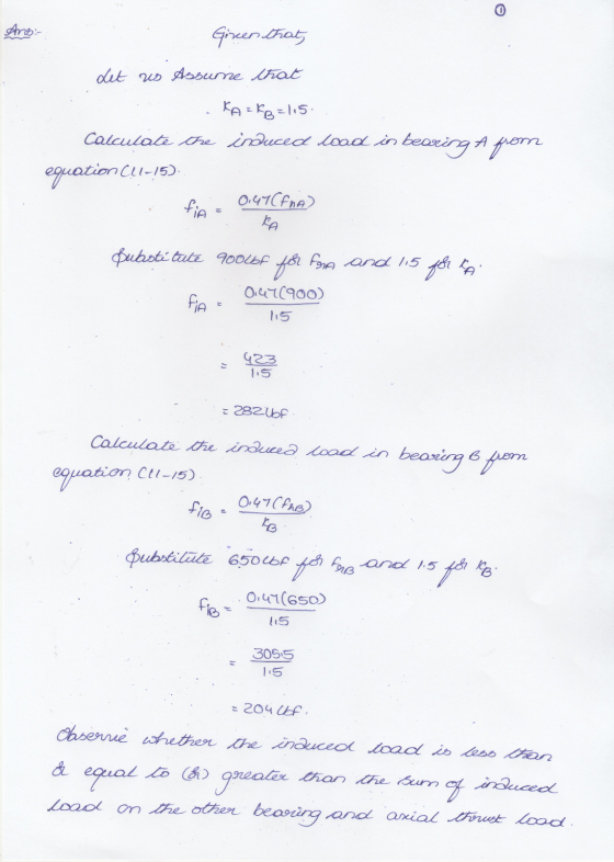
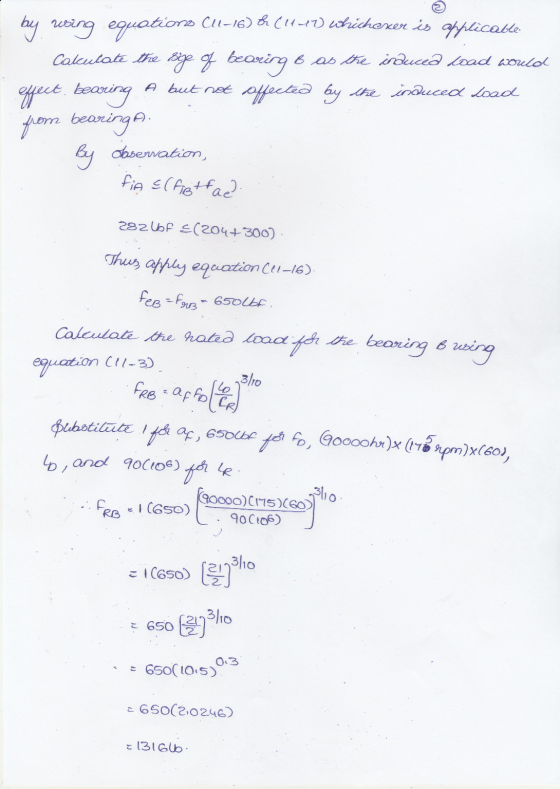
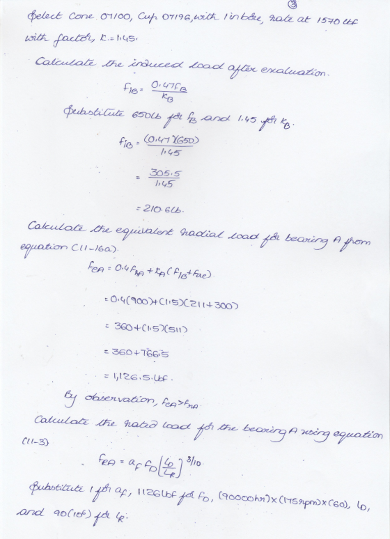
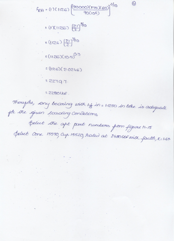
11-32 The figure shown is a geared countershaft with an overhanging pinion at C. Select an...
 11-32 The figure shown is a geared countershaft with an overhanging pinion at C. Select an angular- contact ball bearing from Table 11-2 for mounting at O and an 02-series cylindrical roller bearing from Table 11-3 for mounting at B. The force on gear A is FA-600 lbf, and the shaft is to run at a speed of 420 rev/min. Solution of the statics problem gives force of bear- ings against the shaft at O as Ro--387] 467k lbf, and...
 7-25 A shaft is to be designed to support the spur pinion and helical gear shown in the figure on two bearings spaced 700 mm center-to-center. Bearing A is a cylindrical roller and is to take only radial load; bearingB is to take the thrust load of 900 N produced by the helical gear and its share of the radial load. The bearing at B can be a bal bearing. The radial loads of both gears are in the same...
 is the factor of safety guarding against damaging distortion? What is the factor of safety guard- ing against a fatigue failure? If the shaft turns out to be unsatisfactory, what would you rec- ommend to correct the problem? A shaft is to be designed to support the spur pinion and helical gear shown in th two bearings spaced 28 in center-to-center. Bearing A is a cylindrical roller and is to take only radial load; bearing B is to take the...
 can you please explain how to calculate the axial load for
each gear and supporting load for each bearing? thank you!
Task 1: A shaft is to be designed to support the spur pinion and helical gear shown in the figure below on two bearings spaced 700 mm center-to-center. Bearing A is a cylindrical roller bearing and has to take only radial load; bearing B has to take the thrust load produced by the helical gear and its share of...
can you please explain how to calculate the axial load for
each gear and supporting load for each bearing? thank you!
Task 1: A shaft is to be designed to support the spur pinion and helical gear shown in the figure below on two bearings spaced 700 mm center-to-center. Bearing A is a cylindrical roller bearing and has to take only radial load; bearing B has to take the thrust load produced by the helical gear and its share of...
 A straight-bevel gear mesh is utilized to transform the rotation
about a horizontal shaft of a motor-driven pinion into rotation of
an output gear about a vertical shaft as shown in Fig. 1. The
pressure angle f = 20°. The pinion shaft rotates at 900 rpm.
a. Both pinion and gear are Grade 2 steel through-hardened at
250 Brinell and are uncrowned. The quality number is 9 and the
desired life is 30,000 hours with a 0.999 reliability. For a...
A straight-bevel gear mesh is utilized to transform the rotation
about a horizontal shaft of a motor-driven pinion into rotation of
an output gear about a vertical shaft as shown in Fig. 1. The
pressure angle f = 20°. The pinion shaft rotates at 900 rpm.
a. Both pinion and gear are Grade 2 steel through-hardened at
250 Brinell and are uncrowned. The quality number is 9 and the
desired life is 30,000 hours with a 0.999 reliability. For a...
 QUESTION 10 The shaft shown in the figure is driven by a gear at the right keyway, drives a fan at the left keyway, and is supported by two deep-groove ball bearings at locations A and B. The shaft is made from AISI 1045 cold-drawn steel. At steady-state speed, the gear transmits a radial load of 300 lbf and a tangential load of 700 lbf at a pitch diameter of 8 in. Assume that the weight and axial load of...
 The shaft shown in the figure is driven by a gear at the right keyway, drives a fan at the left keyway, and is supported by two deep-groove ball bearings at locations A and B. The shaft is made from AISI 1045 cold-drawn steel. At steady-state speed, the gear transmits a radial load of 300 lbf and a tangential load of 700 lbf at a pitch diameter of 8 in. Assume that the weight and axial load of the fan...
 The shaft shown in the figure is driven by a gear at the right keyway, drives a fan at the left keyway, and is supported by two deep-groove ball bearings at locations A and B. The shaft is made from AISI 1045 cold-drawn steel. At steady-state speed, the gear transmits a radial load of 300 lbf and a tangential load of 700 lbf at a pitch diameter of 8 in. Assume that the weight and axial load of the fan...
 Question 2 The shaft shown below is rotating at 650 rpm, and it receives 7.5 hp through a flexible coupling. The power is delivered to an adjacent shaft through a single helical gear B having a normal pressure angle of 20 degrees and a helix angle of 15 degrees. The pitch diameter for the gear is 4.141 inches (De) and the Tangential (Wu), radial (W) and axial/thrust (W) are shown below on the drawing. The shaft is to be made...
 Figure below shows the load components acting on a helical gear
mounted on a simply
supported shaft. Bearing B takes thrust. A flexible coupling for
transmitting
torque attaches to the right end of the shaft. The left end is
free.
1-Draw load, shear force, and bending moment diagrams for the
shaft, in both the horizontal and vertical planes.
2- Identify the most critically loaded shaft cross section, and
for this location determine the diameter theoretically required for
infinite life. Assume...
Figure below shows the load components acting on a helical gear
mounted on a simply
supported shaft. Bearing B takes thrust. A flexible coupling for
transmitting
torque attaches to the right end of the shaft. The left end is
free.
1-Draw load, shear force, and bending moment diagrams for the
shaft, in both the horizontal and vertical planes.
2- Identify the most critically loaded shaft cross section, and
for this location determine the diameter theoretically required for
infinite life. Assume...
 11-32 The figure shown is a geared countershaft with an overhanging pinion at C. Select an angular- contact ball bearing from Table 11-2 for mounting at O and an 02-series cylindrical roller bearing from Table 11-3 for mounting at B. The force on gear A is FA-600 lbf, and the shaft is to run at a speed of 420 rev/min. Solution of the statics problem gives force of bear- ings against the shaft at O as Ro--387] 467k lbf, and...
Most questions answered within 3 hours.
-
A munitions warehouse contains 50 bombs, of which 3 are
defective (6%). A sample of 10...
asked 11 minutes ago -
List 6 factors you should consider when designing indexes.
Please explain your answers.
asked 9 minutes ago -
Hello
I am beginner in JAVA but that does not mean i
cant do a perfect...
asked 6 minutes ago -
is
it possible for a change in one nucleotide of an organism’s DNA to
result in...
asked 39 minutes ago -
Project 5 - intro to python
Write a program in python that calculates the amount of...
asked 34 minutes ago -
Compare/Contrast the following: protein/enzyme, ligand/substrate,
channel protein/carrier protein,
exocytosis/endocytosis.
asked 45 minutes ago -
A researcher asks: Are high school students who have tried
alcohol more likely to have had...
asked 47 minutes ago -
Use a style sheet to define the following rules and implement
the given HTML code. Please...
asked 48 minutes ago -
How many grams of KBr are contained in 200 mL of a 0.310 M KBr
solution?...
asked 51 minutes ago -
The three most valuable (in terms of current exploitation)
marine physical resources in order from most...
asked 1 hour ago -
Please answer the below 3 problems and show your work.
a. P(-1.45 < Z < .98)...
asked 1 hour ago -
Discuss in 500 words your opinion on what lessons should be
learned from the 737 Max...
asked 1 hour ago