

Homework Answers
Solution:- The given problem has been solved using standard formulas for calculating the shear forces and bending moments. Usual notations have been followed.
Add Answer to:
Question 2 The shaft shown below is rotating at 650 rpm, and it receives 7.5 hp...
please solve with details Question#1140Marksl The shaft shown in the figure is rotating at 650 rpm and it receives 5592.75 W through a flexible coupling at its right end. The power is delivered t...
 please solve with details
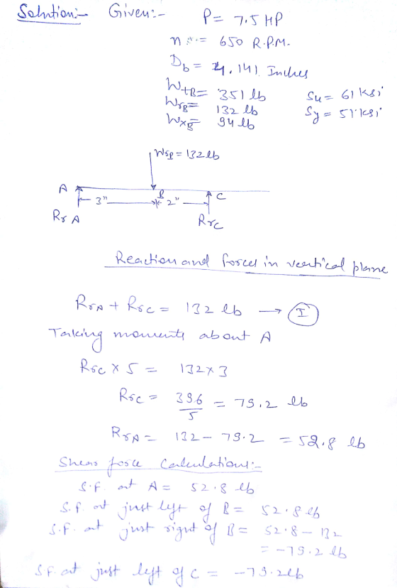
Question#1140Marksl The shaft shown in the figure is rotating at 650 rpm and it receives 5592.75 W through a flexible coupling at its right end. The power is delivered to an adjacent shaft through a single helical gear B having a normal pressure angle of 20° and a helix angle of 15o. The pitch diameter for the gear is 105.1814 mm (4.141 in). A spacer is used to position the gear relative to bearing C. The...
please solve with details
Question#1140Marksl The shaft shown in the figure is rotating at 650 rpm and it receives 5592.75 W through a flexible coupling at its right end. The power is delivered to an adjacent shaft through a single helical gear B having a normal pressure angle of 20° and a helix angle of 15o. The pitch diameter for the gear is 105.1814 mm (4.141 in). A spacer is used to position the gear relative to bearing C. The...
Figure below shows the load components acting on a helical gear mounted on a simply supported...
 Figure below shows the load components acting on a helical gear
mounted on a simply
supported shaft. Bearing B takes thrust. A flexible coupling for
transmitting
torque attaches to the right end of the shaft. The left end is
free.
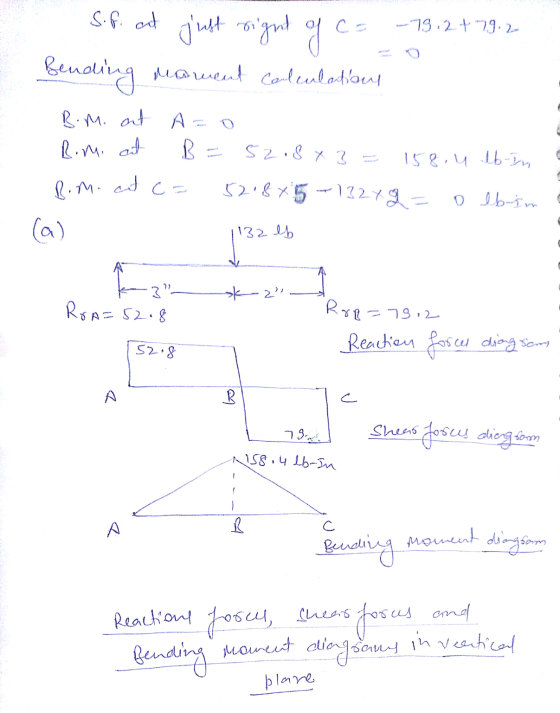
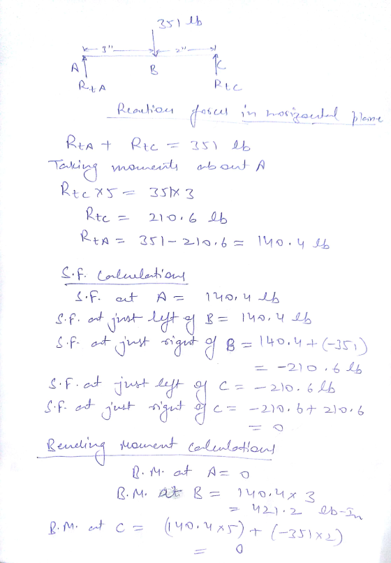
1-Draw load, shear force, and bending moment diagrams for the
shaft, in both the horizontal and vertical planes.
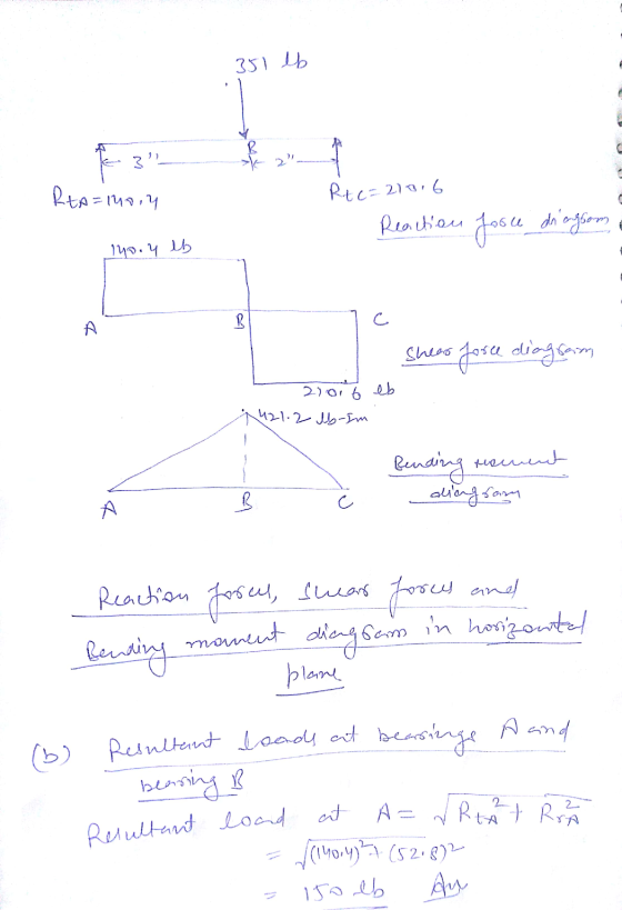
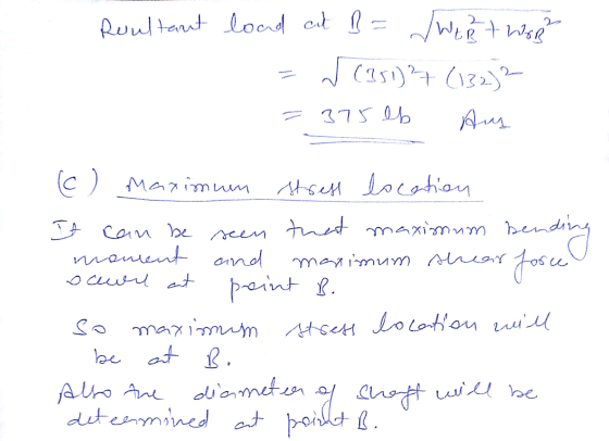
2- Identify the most critically loaded shaft cross section, and
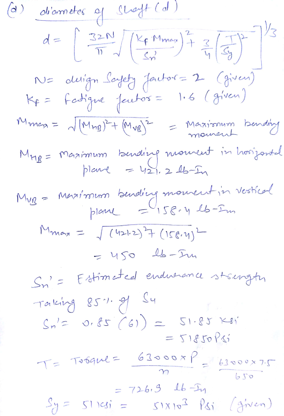
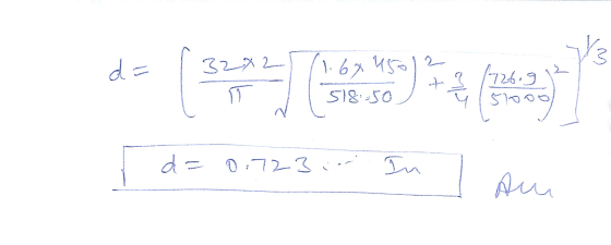
for this location determine the diameter theoretically required for
infinite life. Assume...
Figure below shows the load components acting on a helical gear
mounted on a simply
supported shaft. Bearing B takes thrust. A flexible coupling for
transmitting
torque attaches to the right end of the shaft. The left end is
free.
1-Draw load, shear force, and bending moment diagrams for the
shaft, in both the horizontal and vertical planes.
2- Identify the most critically loaded shaft cross section, and
for this location determine the diameter theoretically required for
infinite life. Assume...
QUESTION 9 A line shaft rotating at speed to transmit power through torque equal to 911...
 QUESTION 9 A line shaft rotating at speed to transmit power through torque equal to 911 N.m. The shaft is made of mild steel with an allowable shear stress of 68 MPa. Neglecting the effect of bending moment on the shaft. Compute the diameter of the shaft (mm)? QUESTION 11 A gear carried by a shaft exerts a force on the shaft. The torque transmitted by the gear is equal to 377,890 N.mm. The Pitch diameter of the gear is...
0.2) Figure Q.2 shows a drive system in which a 20-hp electric motor drives separate output shaft...
 Desgin
0.2) Figure Q.2 shows a drive system in which a 20-hp electric motor drives separate output shafts. Gear A is mounted on the motor shafit that has a rotational spoed or 1750 rpm clockwise. Gear A drives gear train consisting of…B,C,and D thr deliver power through the shafts on which they are mounted. All gears have a diametral pitch of Pa-8.The following data are given Power delivered by gears B, C, and D: Pa Numbers of teeth for all...
Desgin
0.2) Figure Q.2 shows a drive system in which a 20-hp electric motor drives separate output shafts. Gear A is mounted on the motor shafit that has a rotational spoed or 1750 rpm clockwise. Gear A drives gear train consisting of…B,C,and D thr deliver power through the shafts on which they are mounted. All gears have a diametral pitch of Pa-8.The following data are given Power delivered by gears B, C, and D: Pa Numbers of teeth for all...
1: Given the power transmission system shown below Input: 30 hp, 2,000 rpm 12 pitch 18...
 1: Given the power transmission system shown below Input: 30 hp, 2,000 rpm 12 pitch 18 teeth N C Rotation Hydraulic Pump 5 hp Water Pump, 6 hp 20° pressure angle 8 pitch 20 teeth 20° pressure angle 27 teeth 40 teeth Input Pump Output Bearing (typical) p (NP) Find: A Determine the rotation direction, rotational speed, and pitch diameter of each gear Pitch Diameter (in) Rotational Speed (rpm) Gear 1333 rmp B. Determine the hp and torque in shaft...
The rotating solid steel shaft is simply supported by bearings at points B and C and is driven by gear (not shown) which meshes with the spur gear at D
 The rotating solid steel shaft is simply supported by bearings at points B and C and is driven by gear (not shown) which meshes with the spur gear at D, which has a 150-mm pitch diameter. The force F from the drive gear acts at a pressure angle of 20". The shaft transmits a torque to point A of TA = 340 N.m. The shaft is machined from steel with Sy= 420 MPa and Sut = 560 MPa. The fatigue...
A transfer shaft with two spur gears shown below: Input Gear 1 Output Gear Torque Bearing...
 A transfer shaft with two spur gears shown below: Input Gear 1 Output Gear Torque Bearing 1 Gear 1 Gear 2 Bearing 2 B OTO 4" 4" 4" 4 . . Weight Ibf Teeth number Pressure angle Po (diametric pitch) teeth/in Gear A 50 20° 6 Gear C 2 25 20° 6 Deep groove ball bearings at B and D. Pitch diameter of the gear is equal to the teeth number divided by diametric pitch. Shaft speed = 3000 rpm....
2.The shaft shown in the figure is driven by a gear at the right keyways, drive...
 2.The shaft shown in the figure is driven by a gear at the right keyways, drive a fan at eh left keyways, and supported by two deep grove ball bearings. The shaft is made of AISI 1020 cold- drawn steel. At steady state speed, the gear transmits a radial load of 230 Ibf and a tangential load of 633 Ibf at pitch diameter of 8 inch. Determine fatigue factor of safety at any potentially critical locations using the DE-Gerber failure...
Y=3390 Q=90 The double reduction helical gear reducer shown in Figure 2 transmits 40000+4Y W (Y...
 Y=3390
Q=90
The double reduction helical gear reducer shown in Figure 2 transmits 40000+4Y W (Y is the last 4 digits of your student identification number). Shaft 1 is the input, rotating at 200+o rad/s and receiving power directly from the electric motor through a flexible coupling. Shaft 2 rotates at 90+ q rad/s. shaft 3 is the output, rotating at 27+Q rad/s. (where Q are the last two digits of your student identification number). A chain sprocket is mounted...
Y=3390
Q=90
The double reduction helical gear reducer shown in Figure 2 transmits 40000+4Y W (Y is the last 4 digits of your student identification number). Shaft 1 is the input, rotating at 200+o rad/s and receiving power directly from the electric motor through a flexible coupling. Shaft 2 rotates at 90+ q rad/s. shaft 3 is the output, rotating at 27+Q rad/s. (where Q are the last two digits of your student identification number). A chain sprocket is mounted...
Question 1 Time Allowed: 2 hours The figure shows a transmission shaft. The steel solid shaft...
 Question 1 Time Allowed: 2 hours The figure shows a transmission shaft. The steel solid shaft is 200 mm long between self-aligning bearings at A and B. Belt forces (in the same horizontal direction) are applied to a 120-mm diameter sheave at C. The left end of the shaft is connected to an electric motor attached to a clutch by means of a flexible coupling. Nothing is attach to the right end (it is free). Assuming the shaft has a...
 please solve with details
Question#1140Marksl The shaft shown in the figure is rotating at 650 rpm and it receives 5592.75 W through a flexible coupling at its right end. The power is delivered to an adjacent shaft through a single helical gear B having a normal pressure angle of 20° and a helix angle of 15o. The pitch diameter for the gear is 105.1814 mm (4.141 in). A spacer is used to position the gear relative to bearing C. The...
please solve with details
Question#1140Marksl The shaft shown in the figure is rotating at 650 rpm and it receives 5592.75 W through a flexible coupling at its right end. The power is delivered to an adjacent shaft through a single helical gear B having a normal pressure angle of 20° and a helix angle of 15o. The pitch diameter for the gear is 105.1814 mm (4.141 in). A spacer is used to position the gear relative to bearing C. The...
 Figure below shows the load components acting on a helical gear
mounted on a simply
supported shaft. Bearing B takes thrust. A flexible coupling for
transmitting
torque attaches to the right end of the shaft. The left end is
free.
1-Draw load, shear force, and bending moment diagrams for the
shaft, in both the horizontal and vertical planes.
2- Identify the most critically loaded shaft cross section, and
for this location determine the diameter theoretically required for
infinite life. Assume...
Figure below shows the load components acting on a helical gear
mounted on a simply
supported shaft. Bearing B takes thrust. A flexible coupling for
transmitting
torque attaches to the right end of the shaft. The left end is
free.
1-Draw load, shear force, and bending moment diagrams for the
shaft, in both the horizontal and vertical planes.
2- Identify the most critically loaded shaft cross section, and
for this location determine the diameter theoretically required for
infinite life. Assume...
 QUESTION 9 A line shaft rotating at speed to transmit power through torque equal to 911 N.m. The shaft is made of mild steel with an allowable shear stress of 68 MPa. Neglecting the effect of bending moment on the shaft. Compute the diameter of the shaft (mm)? QUESTION 11 A gear carried by a shaft exerts a force on the shaft. The torque transmitted by the gear is equal to 377,890 N.mm. The Pitch diameter of the gear is...
 Desgin
0.2) Figure Q.2 shows a drive system in which a 20-hp electric motor drives separate output shafts. Gear A is mounted on the motor shafit that has a rotational spoed or 1750 rpm clockwise. Gear A drives gear train consisting of…B,C,and D thr deliver power through the shafts on which they are mounted. All gears have a diametral pitch of Pa-8.The following data are given Power delivered by gears B, C, and D: Pa Numbers of teeth for all...
Desgin
0.2) Figure Q.2 shows a drive system in which a 20-hp electric motor drives separate output shafts. Gear A is mounted on the motor shafit that has a rotational spoed or 1750 rpm clockwise. Gear A drives gear train consisting of…B,C,and D thr deliver power through the shafts on which they are mounted. All gears have a diametral pitch of Pa-8.The following data are given Power delivered by gears B, C, and D: Pa Numbers of teeth for all...
 1: Given the power transmission system shown below Input: 30 hp, 2,000 rpm 12 pitch 18 teeth N C Rotation Hydraulic Pump 5 hp Water Pump, 6 hp 20° pressure angle 8 pitch 20 teeth 20° pressure angle 27 teeth 40 teeth Input Pump Output Bearing (typical) p (NP) Find: A Determine the rotation direction, rotational speed, and pitch diameter of each gear Pitch Diameter (in) Rotational Speed (rpm) Gear 1333 rmp B. Determine the hp and torque in shaft...
 A transfer shaft with two spur gears shown below: Input Gear 1 Output Gear Torque Bearing 1 Gear 1 Gear 2 Bearing 2 B OTO 4" 4" 4" 4 . . Weight Ibf Teeth number Pressure angle Po (diametric pitch) teeth/in Gear A 50 20° 6 Gear C 2 25 20° 6 Deep groove ball bearings at B and D. Pitch diameter of the gear is equal to the teeth number divided by diametric pitch. Shaft speed = 3000 rpm....
 2.The shaft shown in the figure is driven by a gear at the right keyways, drive a fan at eh left keyways, and supported by two deep grove ball bearings. The shaft is made of AISI 1020 cold- drawn steel. At steady state speed, the gear transmits a radial load of 230 Ibf and a tangential load of 633 Ibf at pitch diameter of 8 inch. Determine fatigue factor of safety at any potentially critical locations using the DE-Gerber failure...
 Y=3390
Q=90
The double reduction helical gear reducer shown in Figure 2 transmits 40000+4Y W (Y is the last 4 digits of your student identification number). Shaft 1 is the input, rotating at 200+o rad/s and receiving power directly from the electric motor through a flexible coupling. Shaft 2 rotates at 90+ q rad/s. shaft 3 is the output, rotating at 27+Q rad/s. (where Q are the last two digits of your student identification number). A chain sprocket is mounted...
Y=3390
Q=90
The double reduction helical gear reducer shown in Figure 2 transmits 40000+4Y W (Y is the last 4 digits of your student identification number). Shaft 1 is the input, rotating at 200+o rad/s and receiving power directly from the electric motor through a flexible coupling. Shaft 2 rotates at 90+ q rad/s. shaft 3 is the output, rotating at 27+Q rad/s. (where Q are the last two digits of your student identification number). A chain sprocket is mounted...
 Question 1 Time Allowed: 2 hours The figure shows a transmission shaft. The steel solid shaft is 200 mm long between self-aligning bearings at A and B. Belt forces (in the same horizontal direction) are applied to a 120-mm diameter sheave at C. The left end of the shaft is connected to an electric motor attached to a clutch by means of a flexible coupling. Nothing is attach to the right end (it is free). Assuming the shaft has a...
Most questions answered within 3 hours.
-
Stories about organizational ________ provide important clues
about cultural values and norms.
a. myths
b. heroes...
asked 44 seconds ago -
Explain the criteria used in selecting a target market
BUS220 Retail Management, thank you!
asked 2 minutes ago -
Convert/Calculate the following:
Determine the identity of an elemental gas if 4.55 L weighing
35.4g, under...
asked 6 minutes ago -
Consider the equilibrium C(s)+ CO2(g) ⇌2 CO(g)
A 2.0 L flask contains a mixture of 0.10...
asked 4 minutes ago -
MATLAB
Part 1 – randFloatValue.m This function accepts two numbers,
lower and upper, and returns a...
asked 10 minutes ago -
You have been asked to hide prizes around your house for your
3-year old nephew. His...
asked 12 minutes ago -
Ammonia will decompose into nitrogen and hydrogen at high
temperature. An industrial chemist studying this reaction...
asked 18 minutes ago -
10. Complete the table below
only using hexadecimal numbers:
AL CODE
EBX
EAX
[EAX]
mov eax,...
asked 36 minutes ago -
trust is best established through the combination of ------and
------- .
1. magnanimity and justice
2....
asked 51 minutes ago -
Blood pressure is normally taken on the upper arm at the level
of the heart. Suppose,...
asked 50 minutes ago -
Suppose that the satellite around the earth has an orbit that is
24 KM larger in...
asked 53 minutes ago -
Calculate the [OH (aq)] in limes which have a [H3O*(aq)] of 1.3 x
10 mol/L
asked 51 minutes ago