
Homework Answers

Add Answer to:
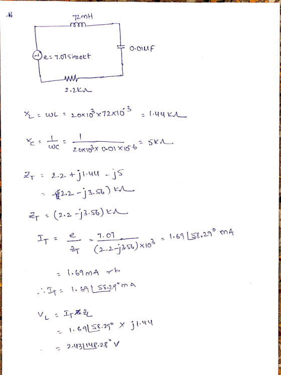
A. Using the rated component values, calculate XL, XC, ZT.
Draw the impedance phasor diagram.
B....
frequency=5000 a) Calculate values for XL,Xc and ZT. b) Calculate I (phasor format) for the circuit....
 frequency=5000
a) Calculate values for XL,Xc and ZT.
b) Calculate I (phasor format) for the circuit.
c) Calculate the voltage (phasor format) drop across the
resistor (VR1), the inductor (VL1 ) and capacitor (Vc1)
xsci L1 15mH 0.033 R1 Fcn Gen RS 50Ω V1 510Ω
frequency=5000
a) Calculate values for XL,Xc and ZT.
b) Calculate I (phasor format) for the circuit.
c) Calculate the voltage (phasor format) drop across the
resistor (VR1), the inductor (VL1 ) and capacitor (Vc1)
xsci L1 15mH 0.033 R1 Fcn Gen RS 50Ω V1 510Ω
ame Su chool Number 4: : The source voltage of the circuit below is V()-140cos(30). The component values are RI-20, XL-30. Xc-20 a) Determine the load impedance Zab that will absorb maximum power if...
 ame Su chool Number 4: : The source voltage of the circuit below is V()-140cos(30). The component values are RI-20, XL-30. Xc-20 a) Determine the load impedance Zab that will absorb maximum power if it is connected to terminals a-b of the circuit below. b) Determine the maximum power absorbed by this load. Xc XL. M-0.8H R1 2-2 0.4H Vit)
ame Su chool Number 4: : The source voltage of the circuit below is V()-140cos(30). The component values are RI-20,...
ame Su chool Number 4: : The source voltage of the circuit below is V()-140cos(30). The component values are RI-20, XL-30. Xc-20 a) Determine the load impedance Zab that will absorb maximum power if it is connected to terminals a-b of the circuit below. b) Determine the maximum power absorbed by this load. Xc XL. M-0.8H R1 2-2 0.4H Vit)
ame Su chool Number 4: : The source voltage of the circuit below is V()-140cos(30). The component values are RI-20,...
for the circuit below: a. Circuit Impedance in polar and rectangular form. b. Is the circuit...
 for the circuit below: a. Circuit Impedance in polar and rectangular form. b. Is the circuit more inductive or more capacitive? c. Draw the impedance phasor diagram. d. The net reactance that will make the impedance magnitude equal to 100 ohms. e. Itot, VR, VL, and VC in polar form. f. Draw the voltage phasor diagram. 47 2 80 2 35 22 4_ov frequency is 5KHz:
Review Part A. Find the relationship between the phasor voltage and phasor current for a resistance...
 Review Part A. Find the relationship between the phasor voltage and phasor current for a resistance The resistor shown here has been transformed into the phasor domain: Ik 4k Suppose that the phasor current is given by IR = 752120 mA. Find the phasor voltage VR. Enter a complex number in polar form, with phase angle in degrees. View Available Hint(s) 3002120 V Submit Previous Answers Correct Part B - Draw the phasor diagram of the resistance from Part A...
9 (12 points) Consider the RLC circuit shown, powered by ε = Vo sin(at). (a) Draw...
 9 (12 points) Consider the RLC circuit shown, powered by ε = Vo sin(at). (a) Draw two phasor diagram, one for the current phasors 11, 12, and I (the total current), and the other for the voltage pahsors V, VI, Vc, and ε. (Hint: Note that I = 11 + 12, while VR = V2 + VC = ε. Draw the phasor diagrams accordingly.) (b) Find I as a function of time. (c) Find the impedance Z of the circuit....
2)Passive Filter: High Pass Filter Lab Experiment 3) Given the following RLC series circuit. V, =...
 2)Passive Filter: High Pass Filter Lab Experiment 3) Given the following RLC series circuit. V, = 10 Vrm L 0º and frequency f= 90 KHz. The circuit elements values are: R = 5 KO, L= 10 mH and C = 470 pF. a) Calculate total impedance Z, in polar form. b) Calculate total current I, in polar form. c) Calculate the voltages across R, C and L, (VR, Vc, and V.). d) Draw voltage phasor diagram Vs, VR, Vc, and...
1. Using circuit 3-1, calculate the total current (which is also the capacitor current and resistor...
 1. Using circuit 3-1, calculate the total current (which is also
the capacitor current and resistor current) by using Ohm’s Law. To
do this, you must first compute the total impedance of the circuit,
in polar form. Also, remember that Vs (source voltage) phase shift
is 0 degrees. Write your answer in polar form.
2. Compute the voltage across the capacitor (C1), using Ohm’s
Law and your result from #1. Write your answer in polar form.
3. In a series...
1. Using circuit 3-1, calculate the total current (which is also
the capacitor current and resistor current) by using Ohm’s Law. To
do this, you must first compute the total impedance of the circuit,
in polar form. Also, remember that Vs (source voltage) phase shift
is 0 degrees. Write your answer in polar form.
2. Compute the voltage across the capacitor (C1), using Ohm’s
Law and your result from #1. Write your answer in polar form.
3. In a series...
I am currently trying to figure out the experiment below. Please complete Table 1 with an...
 I am currently trying to figure out the experiment below. Please
complete Table 1 with an explanation, I appreciate it thank
you! Promise to give thumbs up!
Introduction The phase differences between the output voltage, the voltage across the inductor, the voltage across the capacitor, and the voltage across the resistor will be examined at resonant frequency. The voltage and phase relationship will also be examined for frequencies above and below resonance. Theory An inductor, a capacitor, and a resistor are...
I am currently trying to figure out the experiment below. Please
complete Table 1 with an explanation, I appreciate it thank
you! Promise to give thumbs up!
Introduction The phase differences between the output voltage, the voltage across the inductor, the voltage across the capacitor, and the voltage across the resistor will be examined at resonant frequency. The voltage and phase relationship will also be examined for frequencies above and below resonance. Theory An inductor, a capacitor, and a resistor are...
B oth 100 Day PH262 Page 1 of 5 Lab #13 AC Circuits, Part 1 RC...
 B oth 100 Day PH262 Page 1 of 5 Lab #13 AC Circuits, Part 1 RC & RL, Phase Measurements THEORY The rotating phase representation for series AC circuits should be familiar from textbook and lecture notes A brief outline of the essential points is provided here. If a series RLC circuit is connected across a source of om which is a sinusoidal function of time, then und all its derivatives will also be inside. Sonce all demits in a...
How do you draw the phasor diagram? L=3.3 mH C=0.39 uF R=100 ohms in case you...
 How do you draw the phasor diagram?
L=3.3 mH
C=0.39 uF
R=100 ohms
in case you need it in order to see table 2 work
2. Based on the calculated phase angles Peneos, or Pexp in Table 2, draw a phasor diagram for each of the two frequencies: f = 1000 Hz and 8000 Hz, and complete the following two statements. (a) At f = 8000_Hz, the voltage (1) across the signal generator leads the current (i). (b) At f...
How do you draw the phasor diagram?
L=3.3 mH
C=0.39 uF
R=100 ohms
in case you need it in order to see table 2 work
2. Based on the calculated phase angles Peneos, or Pexp in Table 2, draw a phasor diagram for each of the two frequencies: f = 1000 Hz and 8000 Hz, and complete the following two statements. (a) At f = 8000_Hz, the voltage (1) across the signal generator leads the current (i). (b) At f...
 frequency=5000
a) Calculate values for XL,Xc and ZT.
b) Calculate I (phasor format) for the circuit.
c) Calculate the voltage (phasor format) drop across the
resistor (VR1), the inductor (VL1 ) and capacitor (Vc1)
xsci L1 15mH 0.033 R1 Fcn Gen RS 50Ω V1 510Ω
frequency=5000
a) Calculate values for XL,Xc and ZT.
b) Calculate I (phasor format) for the circuit.
c) Calculate the voltage (phasor format) drop across the
resistor (VR1), the inductor (VL1 ) and capacitor (Vc1)
xsci L1 15mH 0.033 R1 Fcn Gen RS 50Ω V1 510Ω
 ame Su chool Number 4: : The source voltage of the circuit below is V()-140cos(30). The component values are RI-20, XL-30. Xc-20 a) Determine the load impedance Zab that will absorb maximum power if it is connected to terminals a-b of the circuit below. b) Determine the maximum power absorbed by this load. Xc XL. M-0.8H R1 2-2 0.4H Vit)
ame Su chool Number 4: : The source voltage of the circuit below is V()-140cos(30). The component values are RI-20,...
ame Su chool Number 4: : The source voltage of the circuit below is V()-140cos(30). The component values are RI-20, XL-30. Xc-20 a) Determine the load impedance Zab that will absorb maximum power if it is connected to terminals a-b of the circuit below. b) Determine the maximum power absorbed by this load. Xc XL. M-0.8H R1 2-2 0.4H Vit)
ame Su chool Number 4: : The source voltage of the circuit below is V()-140cos(30). The component values are RI-20,...
 for the circuit below: a. Circuit Impedance in polar and rectangular form. b. Is the circuit more inductive or more capacitive? c. Draw the impedance phasor diagram. d. The net reactance that will make the impedance magnitude equal to 100 ohms. e. Itot, VR, VL, and VC in polar form. f. Draw the voltage phasor diagram. 47 2 80 2 35 22 4_ov frequency is 5KHz:
 Review Part A. Find the relationship between the phasor voltage and phasor current for a resistance The resistor shown here has been transformed into the phasor domain: Ik 4k Suppose that the phasor current is given by IR = 752120 mA. Find the phasor voltage VR. Enter a complex number in polar form, with phase angle in degrees. View Available Hint(s) 3002120 V Submit Previous Answers Correct Part B - Draw the phasor diagram of the resistance from Part A...
 9 (12 points) Consider the RLC circuit shown, powered by ε = Vo sin(at). (a) Draw two phasor diagram, one for the current phasors 11, 12, and I (the total current), and the other for the voltage pahsors V, VI, Vc, and ε. (Hint: Note that I = 11 + 12, while VR = V2 + VC = ε. Draw the phasor diagrams accordingly.) (b) Find I as a function of time. (c) Find the impedance Z of the circuit....
 2)Passive Filter: High Pass Filter Lab Experiment 3) Given the following RLC series circuit. V, = 10 Vrm L 0º and frequency f= 90 KHz. The circuit elements values are: R = 5 KO, L= 10 mH and C = 470 pF. a) Calculate total impedance Z, in polar form. b) Calculate total current I, in polar form. c) Calculate the voltages across R, C and L, (VR, Vc, and V.). d) Draw voltage phasor diagram Vs, VR, Vc, and...
 1. Using circuit 3-1, calculate the total current (which is also
the capacitor current and resistor current) by using Ohm’s Law. To
do this, you must first compute the total impedance of the circuit,
in polar form. Also, remember that Vs (source voltage) phase shift
is 0 degrees. Write your answer in polar form.
2. Compute the voltage across the capacitor (C1), using Ohm’s
Law and your result from #1. Write your answer in polar form.
3. In a series...
1. Using circuit 3-1, calculate the total current (which is also
the capacitor current and resistor current) by using Ohm’s Law. To
do this, you must first compute the total impedance of the circuit,
in polar form. Also, remember that Vs (source voltage) phase shift
is 0 degrees. Write your answer in polar form.
2. Compute the voltage across the capacitor (C1), using Ohm’s
Law and your result from #1. Write your answer in polar form.
3. In a series...
 I am currently trying to figure out the experiment below. Please
complete Table 1 with an explanation, I appreciate it thank
you! Promise to give thumbs up!
Introduction The phase differences between the output voltage, the voltage across the inductor, the voltage across the capacitor, and the voltage across the resistor will be examined at resonant frequency. The voltage and phase relationship will also be examined for frequencies above and below resonance. Theory An inductor, a capacitor, and a resistor are...
I am currently trying to figure out the experiment below. Please
complete Table 1 with an explanation, I appreciate it thank
you! Promise to give thumbs up!
Introduction The phase differences between the output voltage, the voltage across the inductor, the voltage across the capacitor, and the voltage across the resistor will be examined at resonant frequency. The voltage and phase relationship will also be examined for frequencies above and below resonance. Theory An inductor, a capacitor, and a resistor are...
 B oth 100 Day PH262 Page 1 of 5 Lab #13 AC Circuits, Part 1 RC & RL, Phase Measurements THEORY The rotating phase representation for series AC circuits should be familiar from textbook and lecture notes A brief outline of the essential points is provided here. If a series RLC circuit is connected across a source of om which is a sinusoidal function of time, then und all its derivatives will also be inside. Sonce all demits in a...
 How do you draw the phasor diagram?
L=3.3 mH
C=0.39 uF
R=100 ohms
in case you need it in order to see table 2 work
2. Based on the calculated phase angles Peneos, or Pexp in Table 2, draw a phasor diagram for each of the two frequencies: f = 1000 Hz and 8000 Hz, and complete the following two statements. (a) At f = 8000_Hz, the voltage (1) across the signal generator leads the current (i). (b) At f...
How do you draw the phasor diagram?
L=3.3 mH
C=0.39 uF
R=100 ohms
in case you need it in order to see table 2 work
2. Based on the calculated phase angles Peneos, or Pexp in Table 2, draw a phasor diagram for each of the two frequencies: f = 1000 Hz and 8000 Hz, and complete the following two statements. (a) At f = 8000_Hz, the voltage (1) across the signal generator leads the current (i). (b) At f...
Most questions answered within 3 hours.
-
DNA to Protein
Describe the mutation that created the HbS allele:
type of mutation, location of...
asked 1 minute ago -
1a)When a 5000-kg roller coaster train full of riders approaches
the loading dock at a speed...
asked 2 minutes ago -
Which attribute allows you to specify a custom "thumbnail" for
multimedia elements?
asked 2 minutes ago -
USE THE FOLLOWING INFORMATION TO ANSWER THE NEXT (6)
QUESTIONS:
The following is a December 31,...
asked 4 minutes ago -
1. Why are the advantages and disadvantages of object-oriented
databases? 2. What are data marts? How...
asked 21 minutes ago -
A Porsche challenges a Honda to a 4.00×10²m race. Because the
Porsche's acceleration of 3.30 m/s2...
asked 22 minutes ago -
A sample of C3H8 has 1.60×1024 H atoms.
How many carbon atoms does the sample contain?...
asked 1 hour ago -
How many unique codes are possibly formed from two characters,
where the first character can be...
asked 44 minutes ago -
A concentration cell is built based on the reaction:
2H+ + 2e- ----> H2
The pH...
asked 40 minutes ago -
what is the ph of the following solutions?
150 g NH4CI dissolved into 10.0 mL of...
asked 51 minutes ago -
A projectile is launched with an initial speed of 40 m/s at an
angle of 25°...
asked 34 minutes ago -
1. Using a function, display the customer who has the highest
credit limit. Display the customer...
asked 43 minutes ago