
Homework Answers


Add Answer to:
for the circuit below: a. Circuit Impedance in polar and rectangular form. b. Is the circuit...
An ac circuit with a 60 μF capacitor in series with a coil of resistance 18Ω...
An ac circuit with a 60 μF capacitor in series with a coil of resistance 18Ω and inductance 180mH is connected to a 100V, 100 Hz supply is shown below. Calculate inductive reactance capacitive reactance circuit impedance and phase angle θ circuit current I phasor voltages VR, VL, VC and VS resonance circuit frequency construct a fully labeled voltage phasor diagram
The circuit shown in Figure 3 below shows a R-L-C series circuit with components R= 50...
 The circuit shown in Figure 3 below shows a R-L-C series circuit with components R= 50 , L = 1 H, and C= 250 uF. This circuit is connected in series to an AC current source ( il ) where instantaneous current is given by it = 28.29 Sin (100t) A. B + VR- C + VC - D ).4C Current source Figure 3 (a) Draw the circuit diagram for this circuit and mark the impedances (3 marks) (b) What...
3. For the circuit shown in Figure 1, + VR - R = 3k 494 ET...
 3. For the circuit shown in Figure 1, + VR - R = 3k 494 ET V 4.7 uF E = 8V sin(20,000t +60° -VL + Z = ? m L = 0.5 H Figure 1 i. ii. iv. v. vi. vii. Find the total impedance Zr in polar form. Draw the impedance diagram Find the current and the voltages VR, Vi and Vc in phasor form. Draw the phasor diagram of the voltages E, VR, V., and Vc and...
INSTRUCTIONS: Read the questions carefully and answer the following items accordingly. Show your solution properly. Q7...
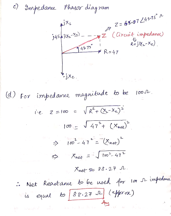
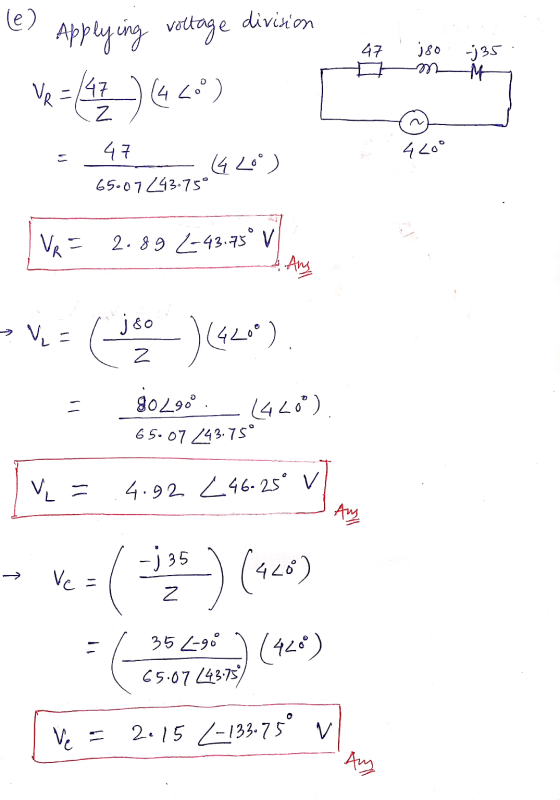
 INSTRUCTIONS: Read the questions carefully and answer the following items accordingly. Show your solution properly. Q7 A technician made an experiment of an AC circuit in an electrical lab. The source voltage is AC with a frequency of 60Hz. He collected the data in the form of a phasor diagram as shown Figure 3. This phasor diagram is an impedance phasor. The values in the diagram are reactances, a resistance and current. The current in this case is the reference...
For the given circuit, a. Find the total admittance and impedance in polar form. b. Find...
 For the given circuit, a. Find the total admittance and impedance in polar form. b. Find the voltage E and currents I_r.I_L., and I_C in phasor form. c. Find the average power delivered to the circuit. d. Find the power factor and indicate if is leading or lagging. e. Find the time domain expressions for the currents and voltage. The total load on a 208 V, 60 Hz supply is 6 KW resistive, 10 kV AR inductive, and 4 kVAR...
Consider an RLC series circuit with R = 600 Ω, L = 3 H, C =...
Consider an RLC series circuit with R = 600 Ω, L = 3 H, C = 4μF, generator voltage V = 20 v, frequency= 60 hz. Find a) the inductive impedance XL, b) capacitive impedance Xc , c) Total impedance Z, d) Line current I , e) Voltage drops VR , VL, ,Vc f) combination voltage VRL , and VLc , g) phase angle φ , h) resonant frequency f0 , i) Power dissipated by circuit.
For the circuit shown, find the impedance and phase angle. Draw an impedance phasor diagram and...
 For the circuit shown, find the impedance and phase angle. Draw an impedance phasor diagram and fill in the table below. Is the circuit inductive, capacitive, or (nearly) purely resistive?
2)Passive Filter: High Pass Filter Lab Experiment 3) Given the following RLC series circuit. V, =...
 2)Passive Filter: High Pass Filter Lab Experiment 3) Given the following RLC series circuit. V, = 10 Vrm L 0º and frequency f= 90 KHz. The circuit elements values are: R = 5 KO, L= 10 mH and C = 470 pF. a) Calculate total impedance Z, in polar form. b) Calculate total current I, in polar form. c) Calculate the voltages across R, C and L, (VR, Vc, and V.). d) Draw voltage phasor diagram Vs, VR, Vc, and...
1. Calculate (a) 24 + j5 + 16+ j10 (b) (4+ j12) x (4 – j12)...
 1. Calculate (a) 24 + j5 + 16+ j10 (b) (4+ j12) x (4 – j12) (c) (4+ j12) + (4 – j12) (d) Convert to rectangular form: 12/10°, 4.242-45° 2. Multiply and Divide the following polar form (a) 45224° x 10454° (b) 184-64° x 42-14° (c) 45224° ÷ 102-10° (d) 5002-72° ÷ 52-12° 150 cos(314t) volts is applied to a pure resistor of R = 30 N 3. A voltage v = (a) Write the expression for i as...
 The circuit shown in Figure 3 below shows a R-L-C series circuit with components R= 50 , L = 1 H, and C= 250 uF. This circuit is connected in series to an AC current source ( il ) where instantaneous current is given by it = 28.29 Sin (100t) A. B + VR- C + VC - D ).4C Current source Figure 3 (a) Draw the circuit diagram for this circuit and mark the impedances (3 marks) (b) What...
 3. For the circuit shown in Figure 1, + VR - R = 3k 494 ET V 4.7 uF E = 8V sin(20,000t +60° -VL + Z = ? m L = 0.5 H Figure 1 i. ii. iv. v. vi. vii. Find the total impedance Zr in polar form. Draw the impedance diagram Find the current and the voltages VR, Vi and Vc in phasor form. Draw the phasor diagram of the voltages E, VR, V., and Vc and...
 INSTRUCTIONS: Read the questions carefully and answer the following items accordingly. Show your solution properly. Q7 A technician made an experiment of an AC circuit in an electrical lab. The source voltage is AC with a frequency of 60Hz. He collected the data in the form of a phasor diagram as shown Figure 3. This phasor diagram is an impedance phasor. The values in the diagram are reactances, a resistance and current. The current in this case is the reference...
 For the given circuit, a. Find the total admittance and impedance in polar form. b. Find the voltage E and currents I_r.I_L., and I_C in phasor form. c. Find the average power delivered to the circuit. d. Find the power factor and indicate if is leading or lagging. e. Find the time domain expressions for the currents and voltage. The total load on a 208 V, 60 Hz supply is 6 KW resistive, 10 kV AR inductive, and 4 kVAR...
 For the circuit shown, find the impedance and phase angle. Draw an impedance phasor diagram and fill in the table below. Is the circuit inductive, capacitive, or (nearly) purely resistive?
 2)Passive Filter: High Pass Filter Lab Experiment 3) Given the following RLC series circuit. V, = 10 Vrm L 0º and frequency f= 90 KHz. The circuit elements values are: R = 5 KO, L= 10 mH and C = 470 pF. a) Calculate total impedance Z, in polar form. b) Calculate total current I, in polar form. c) Calculate the voltages across R, C and L, (VR, Vc, and V.). d) Draw voltage phasor diagram Vs, VR, Vc, and...
 1. Calculate (a) 24 + j5 + 16+ j10 (b) (4+ j12) x (4 – j12) (c) (4+ j12) + (4 – j12) (d) Convert to rectangular form: 12/10°, 4.242-45° 2. Multiply and Divide the following polar form (a) 45224° x 10454° (b) 184-64° x 42-14° (c) 45224° ÷ 102-10° (d) 5002-72° ÷ 52-12° 150 cos(314t) volts is applied to a pure resistor of R = 30 N 3. A voltage v = (a) Write the expression for i as...
Most questions answered within 3 hours.
-
Which of the following statements are true?
1. Glass is mostly silicon dioxide and so when...
asked 17 minutes ago -
Korman Company has the following securities in its portfolio of
equity securities on December 31, 2018:...
asked 17 minutes ago -
Using the 12th edition of Language Awareness,
complete the following assignment:
After reading Akiba Solomon's "Thugs....
asked 28 minutes ago -
For all problems assume an effective monthly interest rate of 1%
unless otherwise indicated in the...
asked 39 minutes ago -
Fix all syntax and logical errors for the following program.
Please generate the correct output. //...
asked 47 minutes ago -
The USPS sells money orders identified by an 11 –digit number
x1, x2, …, x11. The...
asked 51 minutes ago -
Provide an example of equilibrium in relation to
Newton’s First and Second Laws. Explain your answer....
asked 52 minutes ago -
You are __________ to commit a Type I error using the 0.05 level
of significance than...
asked 1 hour ago -
1. the following results are obtained:
200
kiwi
575 wild-type
What can we conclude about the...
asked 1 hour ago -
Explain how you might use E. coli bacteria to produce human
growth hormone using the following:...
asked 1 hour ago -
WHAT IS THE EFFEKT OF ADD K2CO3 TO ( METHANOL OG WATER)?
asked 1 hour ago -
Calculate the cell potential, the equilibrium constant, and the
free-energy change for: Ca(s)+Mn2+(aq)(1M)⇌Ca2+(aq)(1M)+Mn(s) given
the following...
asked 1 hour ago