
Homework Answers
You have the following circuit in sinusoidal steady-state. Use phasor circuit analysis to find the time...
 You have the following circuit in sinusoidal
steady-state.
Use phasor circuit analysis to find the time domain expression
for the steady-state current, i(t), and steady-state voltages,
VR(t), VC(t) and VL(t).
Vs(t) = 50 cos(1000t) Volts.
Problem 1 (20 points) You have the following circuit in sinusoidal steady-state. Use phasor circuit analysis to find the time domain expression for the steady-state current, i(t), and steady- state voltages, Vr(t), Vc(t) and Vl(t). Vs(t) = 50 cos(1000t) Volts. i(t) 100 12 25 mH...
You have the following circuit in sinusoidal
steady-state.
Use phasor circuit analysis to find the time domain expression
for the steady-state current, i(t), and steady-state voltages,
VR(t), VC(t) and VL(t).
Vs(t) = 50 cos(1000t) Volts.
Problem 1 (20 points) You have the following circuit in sinusoidal steady-state. Use phasor circuit analysis to find the time domain expression for the steady-state current, i(t), and steady- state voltages, Vr(t), Vc(t) and Vl(t). Vs(t) = 50 cos(1000t) Volts. i(t) 100 12 25 mH...
for the circuit below: a. Circuit Impedance in polar and rectangular form. b. Is the circuit...
 for the circuit below: a. Circuit Impedance in polar and rectangular form. b. Is the circuit more inductive or more capacitive? c. Draw the impedance phasor diagram. d. The net reactance that will make the impedance magnitude equal to 100 ohms. e. Itot, VR, VL, and VC in polar form. f. Draw the voltage phasor diagram. 47 2 80 2 35 22 4_ov frequency is 5KHz:
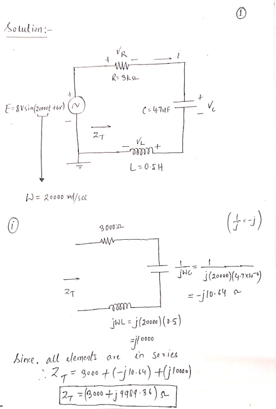
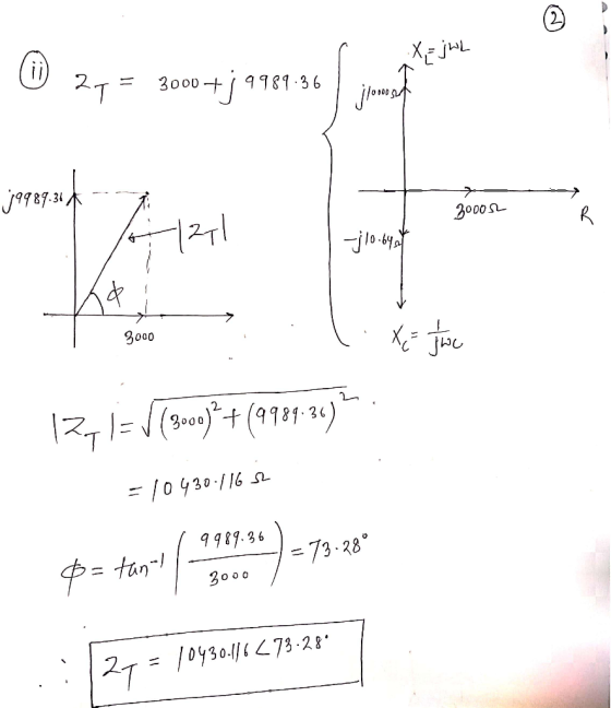
9 (12 points) Consider the RLC circuit shown, powered by ε = Vo sin(at). (a) Draw...
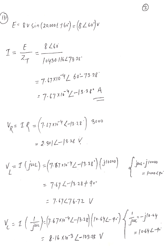
 9 (12 points) Consider the RLC circuit shown, powered by ε = Vo sin(at). (a) Draw two phasor diagram, one for the current phasors 11, 12, and I (the total current), and the other for the voltage pahsors V, VI, Vc, and ε. (Hint: Note that I = 11 + 12, while VR = V2 + VC = ε. Draw the phasor diagrams accordingly.) (b) Find I as a function of time. (c) Find the impedance Z of the circuit....
2)Passive Filter: High Pass Filter Lab Experiment 3) Given the following RLC series circuit. V, =...
 2)Passive Filter: High Pass Filter Lab Experiment 3) Given the following RLC series circuit. V, = 10 Vrm L 0º and frequency f= 90 KHz. The circuit elements values are: R = 5 KO, L= 10 mH and C = 470 pF. a) Calculate total impedance Z, in polar form. b) Calculate total current I, in polar form. c) Calculate the voltages across R, C and L, (VR, Vc, and V.). d) Draw voltage phasor diagram Vs, VR, Vc, and...
An ac circuit with a 60 μF capacitor in series with a coil of resistance 18Ω...
An ac circuit with a 60 μF capacitor in series with a coil of resistance 18Ω and inductance 180mH is connected to a 100V, 100 Hz supply is shown below. Calculate inductive reactance capacitive reactance circuit impedance and phase angle θ circuit current I phasor voltages VR, VL, VC and VS resonance circuit frequency construct a fully labeled voltage phasor diagram
Use the circuit below to complete the given MATLAB script to plot the three voltages Vr,...
 Use the circuit below to complete the given MATLAB script to
plot the three voltages Vr, Vc and VL. Run MATLAB then pick an
answer from the choices below that matches the MATLAB plot.
MATLAB uncomplete script
clc; close all; clear all;
Mvs= 10;
Avs=30*pi/180;
[Xvs Yvs]=pol2cart(Avs, Mvs);
Vs=Xvs+j*Yvs;
% Impedances values
Zr=4; ZL=10j; Zc=-12j;
% total equivalent impedance of series R, L and C
Zeq = ; %complete
% Calculate current
It = ; %complete
Vr= ; %complete
Vc=...
Use the circuit below to complete the given MATLAB script to
plot the three voltages Vr, Vc and VL. Run MATLAB then pick an
answer from the choices below that matches the MATLAB plot.
MATLAB uncomplete script
clc; close all; clear all;
Mvs= 10;
Avs=30*pi/180;
[Xvs Yvs]=pol2cart(Avs, Mvs);
Vs=Xvs+j*Yvs;
% Impedances values
Zr=4; ZL=10j; Zc=-12j;
% total equivalent impedance of series R, L and C
Zeq = ; %complete
% Calculate current
It = ; %complete
Vr= ; %complete
Vc=...
The circuit shown in Figure 3 below shows a R-L-C series circuit with components R= 50...
 The circuit shown in Figure 3 below shows a R-L-C series circuit with components R= 50 , L = 1 H, and C= 250 uF. This circuit is connected in series to an AC current source ( il ) where instantaneous current is given by it = 28.29 Sin (100t) A. B + VR- C + VC - D ).4C Current source Figure 3 (a) Draw the circuit diagram for this circuit and mark the impedances (3 marks) (b) What...
8–31 A voltage vs(t) = 50 cos (5000t) V is applied to the circuit in Figure...
 8–31 A voltage vs(t) = 50 cos (5000t) V is applied to the circuit in Figure P8–31. (a) Convert the circuit into the phasor domain. (b) Find the phasor current flowing through the circuit and the phasor voltages across the inductor and the resistor. (c) Plot all three phasors from (b) on a phasor diagram. Describe if the current leads or lags the inductor voltage. i(t) 50 22 25 mH 00 + VL(t) - + Vr(t)- vs(t) (+) FIGURE P8-31
find the current i and the voltages vr and vl in flphaser form Electrical Engineering Dpt....
 find the current i and the voltages vr and vl in
flphaser form
Electrical Engineering Dpt. UQU Circuit Analysis - (8021010) Chapter#15 R = 80 X = 60 000 1# Find the current I and the voltages VRand Vlin phasor form. E = 100 V ZO
find the current i and the voltages vr and vl in
flphaser form
Electrical Engineering Dpt. UQU Circuit Analysis - (8021010) Chapter#15 R = 80 X = 60 000 1# Find the current I and the voltages VRand Vlin phasor form. E = 100 V ZO
 You have the following circuit in sinusoidal
steady-state.
Use phasor circuit analysis to find the time domain expression
for the steady-state current, i(t), and steady-state voltages,
VR(t), VC(t) and VL(t).
Vs(t) = 50 cos(1000t) Volts.
Problem 1 (20 points) You have the following circuit in sinusoidal steady-state. Use phasor circuit analysis to find the time domain expression for the steady-state current, i(t), and steady- state voltages, Vr(t), Vc(t) and Vl(t). Vs(t) = 50 cos(1000t) Volts. i(t) 100 12 25 mH...
You have the following circuit in sinusoidal
steady-state.
Use phasor circuit analysis to find the time domain expression
for the steady-state current, i(t), and steady-state voltages,
VR(t), VC(t) and VL(t).
Vs(t) = 50 cos(1000t) Volts.
Problem 1 (20 points) You have the following circuit in sinusoidal steady-state. Use phasor circuit analysis to find the time domain expression for the steady-state current, i(t), and steady- state voltages, Vr(t), Vc(t) and Vl(t). Vs(t) = 50 cos(1000t) Volts. i(t) 100 12 25 mH...
 for the circuit below: a. Circuit Impedance in polar and rectangular form. b. Is the circuit more inductive or more capacitive? c. Draw the impedance phasor diagram. d. The net reactance that will make the impedance magnitude equal to 100 ohms. e. Itot, VR, VL, and VC in polar form. f. Draw the voltage phasor diagram. 47 2 80 2 35 22 4_ov frequency is 5KHz:
 9 (12 points) Consider the RLC circuit shown, powered by ε = Vo sin(at). (a) Draw two phasor diagram, one for the current phasors 11, 12, and I (the total current), and the other for the voltage pahsors V, VI, Vc, and ε. (Hint: Note that I = 11 + 12, while VR = V2 + VC = ε. Draw the phasor diagrams accordingly.) (b) Find I as a function of time. (c) Find the impedance Z of the circuit....
 2)Passive Filter: High Pass Filter Lab Experiment 3) Given the following RLC series circuit. V, = 10 Vrm L 0º and frequency f= 90 KHz. The circuit elements values are: R = 5 KO, L= 10 mH and C = 470 pF. a) Calculate total impedance Z, in polar form. b) Calculate total current I, in polar form. c) Calculate the voltages across R, C and L, (VR, Vc, and V.). d) Draw voltage phasor diagram Vs, VR, Vc, and...
 Use the circuit below to complete the given MATLAB script to
plot the three voltages Vr, Vc and VL. Run MATLAB then pick an
answer from the choices below that matches the MATLAB plot.
MATLAB uncomplete script
clc; close all; clear all;
Mvs= 10;
Avs=30*pi/180;
[Xvs Yvs]=pol2cart(Avs, Mvs);
Vs=Xvs+j*Yvs;
% Impedances values
Zr=4; ZL=10j; Zc=-12j;
% total equivalent impedance of series R, L and C
Zeq = ; %complete
% Calculate current
It = ; %complete
Vr= ; %complete
Vc=...
Use the circuit below to complete the given MATLAB script to
plot the three voltages Vr, Vc and VL. Run MATLAB then pick an
answer from the choices below that matches the MATLAB plot.
MATLAB uncomplete script
clc; close all; clear all;
Mvs= 10;
Avs=30*pi/180;
[Xvs Yvs]=pol2cart(Avs, Mvs);
Vs=Xvs+j*Yvs;
% Impedances values
Zr=4; ZL=10j; Zc=-12j;
% total equivalent impedance of series R, L and C
Zeq = ; %complete
% Calculate current
It = ; %complete
Vr= ; %complete
Vc=...
 The circuit shown in Figure 3 below shows a R-L-C series circuit with components R= 50 , L = 1 H, and C= 250 uF. This circuit is connected in series to an AC current source ( il ) where instantaneous current is given by it = 28.29 Sin (100t) A. B + VR- C + VC - D ).4C Current source Figure 3 (a) Draw the circuit diagram for this circuit and mark the impedances (3 marks) (b) What...
 8–31 A voltage vs(t) = 50 cos (5000t) V is applied to the circuit in Figure P8–31. (a) Convert the circuit into the phasor domain. (b) Find the phasor current flowing through the circuit and the phasor voltages across the inductor and the resistor. (c) Plot all three phasors from (b) on a phasor diagram. Describe if the current leads or lags the inductor voltage. i(t) 50 22 25 mH 00 + VL(t) - + Vr(t)- vs(t) (+) FIGURE P8-31
 find the current i and the voltages vr and vl in
flphaser form
Electrical Engineering Dpt. UQU Circuit Analysis - (8021010) Chapter#15 R = 80 X = 60 000 1# Find the current I and the voltages VRand Vlin phasor form. E = 100 V ZO
find the current i and the voltages vr and vl in
flphaser form
Electrical Engineering Dpt. UQU Circuit Analysis - (8021010) Chapter#15 R = 80 X = 60 000 1# Find the current I and the voltages VRand Vlin phasor form. E = 100 V ZO
Most questions answered within 3 hours.
-
Assume one of your finals has 50 questions on it, and
lucky for you, it's all...
asked 40 minutes ago -
Rice Products in Bangladesh
Business behavior is derived in large part from the basic cultural
environment...
asked 2 hours ago -
The following base sequence is found for a mRNA fragment from
wild-type E. coli: 5'- UAUCAGUAGAUAAUGUAACC-3'...
asked 2 hours ago -
For this exercise, round all regression parameters to three
decimal places.
One of the two tables...
asked 2 hours ago -
What is the 5% level of significance for mean = 3.60, standard
deviation = 0.94, and...
asked 2 hours ago -
Prior to beginning work on this discussion, please read the
article by Hayley Peterson, 15 Companies...
asked 3 hours ago -
Which pair of aqueous solutions, when mixed, will form a
precipitate?
A) NaNO3 and AgC2H3O2
B)...
asked 3 hours ago -
1-Write an algorithm to get two numbers from the user (as
inputs) and calculate the sum...
asked 6 hours ago -
Define white-collar crime. What is the difference between
offender and offense-based definitions of white-collar crime? What...
asked 7 hours ago -
Consider a reaction which is 1st order with respect to A and 1st
order with respect...
asked 7 hours ago -
c++
The length of the hypotenuse of a right-angled triangle is the
square root of the...
asked 7 hours ago -
When a metal rod is heated, not only its resistance but also its
length and cross‐sectional...
asked 7 hours ago