
Homework Answers


simply supported reinforced concrete beam of rectangular section is hung on the left end by a 400mm square post working in tension, as shown in the figure below. The beam supports a uniform dead l...
 simply supported reinforced concrete beam of rectangular section is hung on the left end by a 400mm square post working in tension, as shown in the figure below. The beam supports a uniform dead load (DL) gf 100 KN/m (excluding its own weight) and upiform live load LL) of 40KN/m. The beam is reinforced with 025 longitudinal rebars with 40mm cleat cover to the stirrups. Material properties: fy 420 MPa, fe 25 MPa. Beam dimension b 400mm and h 600mm....
Task 1: (50 Marks) Cross section of a reinforced concrete beam is shown in Figure 1....
 Task 1: (50 Marks) Cross section of a reinforced concrete beam is shown in Figure 1. The following shear forces have been calculated due to Dead Load and Live Load at the support: VDL = 150 kN, ViL = 200 kN. Design the shear reinforcement for the ultimate shear force. Use No. 10 bars for shear reinforcement Assume "fe, = 28 MPa, fyt-420 MPa, b = 300 mm, d = 750 mm, h = 800 mm Figure 1. Beam cross-section
A reinforced concrete cantilevered beam with a span of 5 m extends from the wall, as shown in the...
 A reinforced concrete cantilevered beam with a span of 5 m extends from the wall, as shown in the figure below. The beam has a rectangular cross-section and supports a uniform dead load (DL) of 15 kN/m (excluding the self-weight) and a uniform live load (LL) of 25 kN/m. The beam width is restricted to 400 mm. Use 10M stirrups and 25M bars for tension steel. The maximum aggregate size is 20 mm. 1ie 5.5. beam is located in the...
reinforced concrete design , ACI code Shear Strength of Flexural Members Design for shear forces The...
 reinforced concrete design , ACI code
Shear Strength of Flexural Members Design for shear forces The simply supported beam shown is subjected to ultimate (factored) distributed and concentrated loads 1. Determine the shear capacity of concrete at the critical section according to ACI318-14 detailed method in Table 22.5.5.1. Design the shear reinforcement and determine the locations on the beam shear force diagram where this shear reinforcement should be placed. 2. 3. Determine the locations within the beam where minimum shear...
reinforced concrete design , ACI code
Shear Strength of Flexural Members Design for shear forces The simply supported beam shown is subjected to ultimate (factored) distributed and concentrated loads 1. Determine the shear capacity of concrete at the critical section according to ACI318-14 detailed method in Table 22.5.5.1. Design the shear reinforcement and determine the locations on the beam shear force diagram where this shear reinforcement should be placed. 2. 3. Determine the locations within the beam where minimum shear...
A simply supported reinforced concrete beam of 8 m span is subjected to uniformly distributed load...
 A simply supported reinforced concrete beam of 8 m span is subjected to uniformly distributed load as shown in Figure 3. The following data are given: The ultimate load, wu is 60 kN/m; characteristic strength of concrete, fck is 30 N/mm²; characteristic strength of reinforcement, fyk is 500 N/mm2. The effective depth, d is 650 mm. Take the link diameter, w as 10 mm, main bar diameter, o as 20 mm and concrete cover as 30 mm. Design the shear...
Need help with E and F please. 3. The beam shown in the figure below is...
 Need help with E and F please.
3. The beam shown in the figure below is carrying superimposed dead load of 25 kN/m and use and occupancy load of 45 kN/m. For preliminary analysis, assume a self weight of 10 kN/m. We are required to find the maximum positive (tension at the bottom) and negative (tension at the top) moments due to the factored loads, and then design the beam CIV E 374-RC-Lab 3 Fall 2018 (a) Determine the maximum...
Need help with E and F please.
3. The beam shown in the figure below is carrying superimposed dead load of 25 kN/m and use and occupancy load of 45 kN/m. For preliminary analysis, assume a self weight of 10 kN/m. We are required to find the maximum positive (tension at the bottom) and negative (tension at the top) moments due to the factored loads, and then design the beam CIV E 374-RC-Lab 3 Fall 2018 (a) Determine the maximum...
all parts A simply supported concrete beam is to be designed to span 8m. The beam...
 all parts
A simply supported concrete beam is to be designed to span 8m. The beam is required to resist a dead load of 40 kN/m (which includes an allowance for self-weight) and an imposed load of 20 kN/m Calculate the ultimate design load that the beam will be required to resist and hence calculate the ultimate design moment. (10 Marks] b) Choose an appropriate depth and width of the beam. [5 marks] c) Calculate an appropriate amount of reinforcing...
all parts
A simply supported concrete beam is to be designed to span 8m. The beam is required to resist a dead load of 40 kN/m (which includes an allowance for self-weight) and an imposed load of 20 kN/m Calculate the ultimate design load that the beam will be required to resist and hence calculate the ultimate design moment. (10 Marks] b) Choose an appropriate depth and width of the beam. [5 marks] c) Calculate an appropriate amount of reinforcing...
Figure 2 shows a simply supported beam and the cross section at mid span. The beam...
 Figure 2 shows a simply supported beam and the cross section at mid span. The beam supports a uniform service (unfactored) dead load consisting of its own weight plus 1.4 kips/ft and a uniform service (unfactored) live load of 1.5 kips/ft. The concrete strength is 3500 psi, and the yield strength of the reinforcement is 60,000 psi. The concrete is normal-weight concrete. For the midspan section shown in Figure 2, compute фМп and show that it exceeds Mu. WD 1.4...
A T-beam with a simply supported span of 6m is subjected to a concentrated live load as shown in ...
 A T-beam with a simply supported span of 6m is subjected to a concentrated live load as shown in Figure: the cross-sectional details are given in Figure. Design the beam for shear assuming f-40 MPa, fsy,f 500 MPa 700 kN 1000 100 800 828 8N28 70 300 do Consider unit weight of concrete- 25 kN/m3
A T-beam with a simply supported span of 6m is subjected to a concentrated live load as shown in Figure: the cross-sectional details are given...
A T-beam with a simply supported span of 6m is subjected to a concentrated live load as shown in Figure: the cross-sectional details are given in Figure. Design the beam for shear assuming f-40 MPa, fsy,f 500 MPa 700 kN 1000 100 800 828 8N28 70 300 do Consider unit weight of concrete- 25 kN/m3
A T-beam with a simply supported span of 6m is subjected to a concentrated live load as shown in Figure: the cross-sectional details are given...
a simply supported beam shown has a span length of 16 ft. the beam is laoded...
 a simply supported beam shown has a span length of 16 ft. the
beam is laoded with to concentrated service live loads of 40 kips
and 80 kips as shown. if lateral support is provided only at both
ends, select the lightest w section of A992 steel that can carry
these applied loads. neglect the weight of the beam.
***Need this answered ASAP please***
***Please show ALL steps***
steel design - please show what tables the values come from.
thank...
a simply supported beam shown has a span length of 16 ft. the
beam is laoded with to concentrated service live loads of 40 kips
and 80 kips as shown. if lateral support is provided only at both
ends, select the lightest w section of A992 steel that can carry
these applied loads. neglect the weight of the beam.
***Need this answered ASAP please***
***Please show ALL steps***
steel design - please show what tables the values come from.
thank...
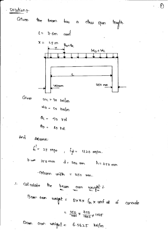
 simply supported reinforced concrete beam of rectangular section is hung on the left end by a 400mm square post working in tension, as shown in the figure below. The beam supports a uniform dead load (DL) gf 100 KN/m (excluding its own weight) and upiform live load LL) of 40KN/m. The beam is reinforced with 025 longitudinal rebars with 40mm cleat cover to the stirrups. Material properties: fy 420 MPa, fe 25 MPa. Beam dimension b 400mm and h 600mm....
 Task 1: (50 Marks) Cross section of a reinforced concrete beam is shown in Figure 1. The following shear forces have been calculated due to Dead Load and Live Load at the support: VDL = 150 kN, ViL = 200 kN. Design the shear reinforcement for the ultimate shear force. Use No. 10 bars for shear reinforcement Assume "fe, = 28 MPa, fyt-420 MPa, b = 300 mm, d = 750 mm, h = 800 mm Figure 1. Beam cross-section
 A reinforced concrete cantilevered beam with a span of 5 m extends from the wall, as shown in the figure below. The beam has a rectangular cross-section and supports a uniform dead load (DL) of 15 kN/m (excluding the self-weight) and a uniform live load (LL) of 25 kN/m. The beam width is restricted to 400 mm. Use 10M stirrups and 25M bars for tension steel. The maximum aggregate size is 20 mm. 1ie 5.5. beam is located in the...
 reinforced concrete design , ACI code
Shear Strength of Flexural Members Design for shear forces The simply supported beam shown is subjected to ultimate (factored) distributed and concentrated loads 1. Determine the shear capacity of concrete at the critical section according to ACI318-14 detailed method in Table 22.5.5.1. Design the shear reinforcement and determine the locations on the beam shear force diagram where this shear reinforcement should be placed. 2. 3. Determine the locations within the beam where minimum shear...
reinforced concrete design , ACI code
Shear Strength of Flexural Members Design for shear forces The simply supported beam shown is subjected to ultimate (factored) distributed and concentrated loads 1. Determine the shear capacity of concrete at the critical section according to ACI318-14 detailed method in Table 22.5.5.1. Design the shear reinforcement and determine the locations on the beam shear force diagram where this shear reinforcement should be placed. 2. 3. Determine the locations within the beam where minimum shear...
 A simply supported reinforced concrete beam of 8 m span is subjected to uniformly distributed load as shown in Figure 3. The following data are given: The ultimate load, wu is 60 kN/m; characteristic strength of concrete, fck is 30 N/mm²; characteristic strength of reinforcement, fyk is 500 N/mm2. The effective depth, d is 650 mm. Take the link diameter, w as 10 mm, main bar diameter, o as 20 mm and concrete cover as 30 mm. Design the shear...
 Need help with E and F please.
3. The beam shown in the figure below is carrying superimposed dead load of 25 kN/m and use and occupancy load of 45 kN/m. For preliminary analysis, assume a self weight of 10 kN/m. We are required to find the maximum positive (tension at the bottom) and negative (tension at the top) moments due to the factored loads, and then design the beam CIV E 374-RC-Lab 3 Fall 2018 (a) Determine the maximum...
Need help with E and F please.
3. The beam shown in the figure below is carrying superimposed dead load of 25 kN/m and use and occupancy load of 45 kN/m. For preliminary analysis, assume a self weight of 10 kN/m. We are required to find the maximum positive (tension at the bottom) and negative (tension at the top) moments due to the factored loads, and then design the beam CIV E 374-RC-Lab 3 Fall 2018 (a) Determine the maximum...
 all parts
A simply supported concrete beam is to be designed to span 8m. The beam is required to resist a dead load of 40 kN/m (which includes an allowance for self-weight) and an imposed load of 20 kN/m Calculate the ultimate design load that the beam will be required to resist and hence calculate the ultimate design moment. (10 Marks] b) Choose an appropriate depth and width of the beam. [5 marks] c) Calculate an appropriate amount of reinforcing...
all parts
A simply supported concrete beam is to be designed to span 8m. The beam is required to resist a dead load of 40 kN/m (which includes an allowance for self-weight) and an imposed load of 20 kN/m Calculate the ultimate design load that the beam will be required to resist and hence calculate the ultimate design moment. (10 Marks] b) Choose an appropriate depth and width of the beam. [5 marks] c) Calculate an appropriate amount of reinforcing...
 Figure 2 shows a simply supported beam and the cross section at mid span. The beam supports a uniform service (unfactored) dead load consisting of its own weight plus 1.4 kips/ft and a uniform service (unfactored) live load of 1.5 kips/ft. The concrete strength is 3500 psi, and the yield strength of the reinforcement is 60,000 psi. The concrete is normal-weight concrete. For the midspan section shown in Figure 2, compute фМп and show that it exceeds Mu. WD 1.4...
 A T-beam with a simply supported span of 6m is subjected to a concentrated live load as shown in Figure: the cross-sectional details are given in Figure. Design the beam for shear assuming f-40 MPa, fsy,f 500 MPa 700 kN 1000 100 800 828 8N28 70 300 do Consider unit weight of concrete- 25 kN/m3
A T-beam with a simply supported span of 6m is subjected to a concentrated live load as shown in Figure: the cross-sectional details are given...
A T-beam with a simply supported span of 6m is subjected to a concentrated live load as shown in Figure: the cross-sectional details are given in Figure. Design the beam for shear assuming f-40 MPa, fsy,f 500 MPa 700 kN 1000 100 800 828 8N28 70 300 do Consider unit weight of concrete- 25 kN/m3
A T-beam with a simply supported span of 6m is subjected to a concentrated live load as shown in Figure: the cross-sectional details are given...
 a simply supported beam shown has a span length of 16 ft. the
beam is laoded with to concentrated service live loads of 40 kips
and 80 kips as shown. if lateral support is provided only at both
ends, select the lightest w section of A992 steel that can carry
these applied loads. neglect the weight of the beam.
***Need this answered ASAP please***
***Please show ALL steps***
steel design - please show what tables the values come from.
thank...
a simply supported beam shown has a span length of 16 ft. the
beam is laoded with to concentrated service live loads of 40 kips
and 80 kips as shown. if lateral support is provided only at both
ends, select the lightest w section of A992 steel that can carry
these applied loads. neglect the weight of the beam.
***Need this answered ASAP please***
***Please show ALL steps***
steel design - please show what tables the values come from.
thank...
Most questions answered within 3 hours.
-
Write a program to solve the Josephus problem, with the following
modification:
Sample Input:
./a.out n...
asked 1 hour ago -
At the start of a CD it is spinning at a rate of 525 rpm
(revolutions...
asked 1 hour ago -
4. Without doing any calculations, predict whether the observed
∆T would increase, decrease or remain the...
asked 2 hours ago -
Based on the range, which of the following sets of scores has
the greatest variability? 3,...
asked 4 hours ago -
Ripples in a pond travel at a velocity of 3 m/s with one peak
passing a...
asked 3 hours ago -
A man stands on the roof of a building of height 13.0 mm and
throws a...
asked 3 hours ago -
The extent to which assets are financed by borrowed funds and
other liabilities is indicated by:...
asked 4 hours ago -
Explain in detail
Germany is the fifth largest economy
explain what goods and services Germany specializes...
asked 5 hours ago -
The density of platinum is 21.45 g/mL. If a cube of platinum
with a mass of...
asked 5 hours ago -
Accounts Receivable
Sales
A/R Posting
Extended Sales Invoice
Packing Slip
Compare invoice to packing slip 2...
asked 5 hours ago -
Michaella, age 23, is a full-time law student and is claimed by
her parents as a...
asked 5 hours ago -
Why are polymers not typically casted into products?
asked 5 hours ago