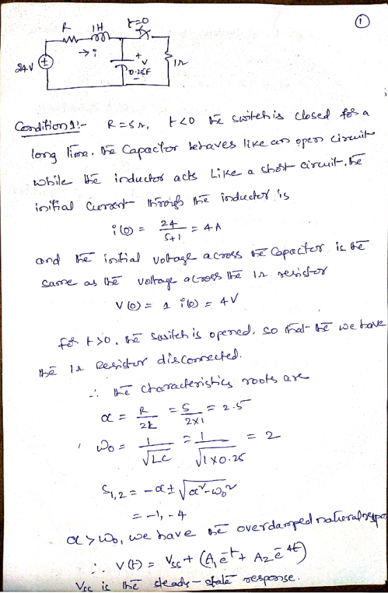
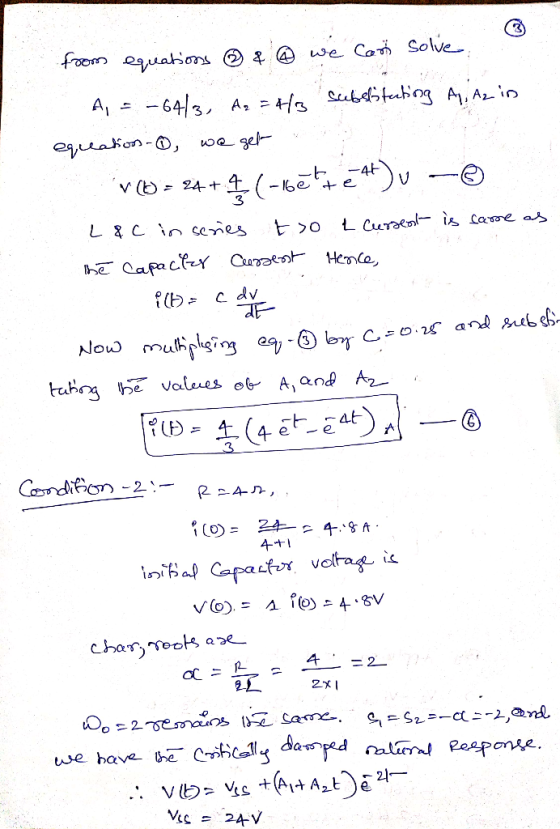
I'm just starting to learn how to analyze RCL circuits so it would be great to have a step by step procedure for solving this problem. Thank you!

Homework Answers


Add Answer to:
I'm just starting to learn how to analyze RCL circuits so it
would be great to...
Learning Goal: Tu learn to evaluate circuits using Krchole laws. All valid electric circuits you will...
 Learning Goal: Tu learn to evaluate circuits using Krchole laws. All valid electric circuits you will analyze and design must satisfy two fundamental laws Kirchhoffe voltage law (KVL) and Kirchhoff's current law (KCL). In this tutorial, you will evaluate circuits using these two laws. Part A - Kirchhoffs voltage law (KVL) For the circuit shown, solve for and Vs when V 48V. V = 1.9V and V -2.75V Express your answer to three significant figures using appropriate units. View Available...
EXPERIMENT 11 STEP RESPONSE TO RC AND RL CIRCUITS pages 11-4 thru 11-7. tep response of the RC an...
 EXPERIMENT 11 STEP RESPONSE TO RC AND RL CIRCUITS pages 11-4 thru 11-7. tep response of the RC and RL circuits is included in OBJECTIVE: O analyze the voltage and current characteristics of a Resistance - Capacitance (RC) circuit when driven by a step voltage function. To analyze the voltage and current characteristics of a Resistance- Inductor (RL) circuit when driven by a step voltage function To design an RC circuit to yield a specified output voltage with a step...
1. RL Circuits For the circuit in Figure 1, find the inductor voltage vit) if a)...
 1. RL Circuits For the circuit in Figure 1, find the inductor voltage vit) if a) v(t) is the step function: 0 Vfor t<0 and 10 V for t>0. What is the time constant in this case? b) vs(t) 15 cos(100 t). You may use either the direct time-domain method, or use (complex) phasor method. 52 102 5mH L(t) Figure 1 2. Impedance You are given six black boxes, labelled "1" to ", each with two terminals. You are told...
Anything would be help please help me OBJECTIVES Study the behavior of capacitors while charging Learn how changing the...
 Anything would be help please help me
OBJECTIVES Study the behavior of capacitors while charging Learn how changing the values of R or C in a series RC circuit affects the charging time Learn the behavior of capacitor and inductor in a DC circuit 1. 2. 3. EQUIPMENT Breadboard, Multimeter, DC power supply, Oscilloscope, Resistor, Capacitor (values will be provided in lab) Connect the given circuit and notice how the capacitor charges Measure the voltage across the resistor, and across...
Anything would be help please help me
OBJECTIVES Study the behavior of capacitors while charging Learn how changing the values of R or C in a series RC circuit affects the charging time Learn the behavior of capacitor and inductor in a DC circuit 1. 2. 3. EQUIPMENT Breadboard, Multimeter, DC power supply, Oscilloscope, Resistor, Capacitor (values will be provided in lab) Connect the given circuit and notice how the capacitor charges Measure the voltage across the resistor, and across...
ANALYSIS Use your experimental results to analyze the circuit in terms of Kirchhoff net current fow...
 ANALYSIS Use your experimental results to analyze the circuit in terms of Kirchhoff net current fow into and out of each of the four nodes, and determine whetheC s Rules. Consider supported by your data. Determine the net voltage drop around at leaston Sign determine whether or not your data supports the loop rule. (Pay close attosed loops convention.) In adition, verify ir Ohm's law is satisfied for at least three resistors and for the total reji >Q12: Why do...
I need help in MATLAB. I'm working on a circuits lab report and I want to...
I need help in MATLAB. I'm working on a circuits lab report and I want to plot the derivative of an input signal. The circuit is a differentiator OpAmp. It is receiving a triangle wave as an input and should output a square wave. (I've included my existing code.) The output formula is: Vout = -(Rf)*C*(dVin/dt) Where Rf is feedback resistance: Rf = 1*10^6; and C = 1*10^-6. EXISTING CODE: %% This section is copied, and then modified from another...
I'm unsure how to work this problem. Please include all drawings where necessary. For the following...
 I'm unsure how to work this problem. Please include
all drawings where necessary.
For the following design C1-0.05F L1-2H R2-40 R1 40 C2-0.05F L2-2H Va-4cos(10t+900)V Vb-4cos(10t+90°] R4-40 L3 0.1H C3-0.1F R3-40Q 1R6-20 vc=4cos( 20t+900)V vd:4cos( 10t+600)V (Remember that i) ω is given in rad/sec, i) the above circuits have different Impedances for different frequencies, ii) we replace the shorted voltage power supplies with a short circuit, İV) with a+jb the rectangular form and NO the polar form we have a-Acos(9),...
I'm unsure how to work this problem. Please include
all drawings where necessary.
For the following design C1-0.05F L1-2H R2-40 R1 40 C2-0.05F L2-2H Va-4cos(10t+900)V Vb-4cos(10t+90°] R4-40 L3 0.1H C3-0.1F R3-40Q 1R6-20 vc=4cos( 20t+900)V vd:4cos( 10t+600)V (Remember that i) ω is given in rad/sec, i) the above circuits have different Impedances for different frequencies, ii) we replace the shorted voltage power supplies with a short circuit, İV) with a+jb the rectangular form and NO the polar form we have a-Acos(9),...
Learning Goal: To use the mesh-current method to analyze circuits containing resistors and independent voltage sources....
 Learning Goal: To use the mesh-current method to analyze circuits containing resistors and independent voltage sources. The mesh-current method is a general technique for solving circuits. Fundamentally, it involves writing KVL equations around all meshes in a circuit. You should review KVL and the definition of a mesh before beginning. In this tutorial, you will use the mesh- current method to find the current through the 1 k2 resistor, io, and the voltage drop across the 5 k22 resistor, vo,...
Learning Goal: To practice Problem-Solving Strategy 23.1 Resistor Circuits. Find the currents through and the potential...
 Learning Goal:
To practice Problem-Solving Strategy 23.1 Resistor Circuits.
Find the currents through and the potential difference across
each resistor in the circuit shown on the diagram (Figure 1) . Use
the following values: E = 12.0V , R1 = 15.0? , R2
= 45.0? , R3 = 20.0? , and R4 = 25.0? .
PROBLEM-SOLVING STRATEGY 23.1 Resistor Circuits
We can analyze any resistor circuit by sequentially reducing
parallel and series resistor combinations to their equivalent
resistors until only...
Learning Goal:
To practice Problem-Solving Strategy 23.1 Resistor Circuits.
Find the currents through and the potential difference across
each resistor in the circuit shown on the diagram (Figure 1) . Use
the following values: E = 12.0V , R1 = 15.0? , R2
= 45.0? , R3 = 20.0? , and R4 = 25.0? .
PROBLEM-SOLVING STRATEGY 23.1 Resistor Circuits
We can analyze any resistor circuit by sequentially reducing
parallel and series resistor combinations to their equivalent
resistors until only...
Could you please show me how I can drw those circuits. please using (NI Multisim 14)...
 Could you please show me how I can drw those circuits.
please using (NI Multisim 14)
Optocoupler Objectives Use an ohmmeter to determine the condition of the optoisolator. Observe the operation of an optocoupler. Determine the maximum frequency response of the optocoupler. Required Materials (1) Dual DC power supply (1) Function generator (1) Oscilloscope (2) Multimeters (1) Optocoupler (ECG3040) (1) 3.9ΚΩ resistor (1) 220 resistor Introduction An optoisolator is a hybrid integrated circuit that contains an LED on one side...
Could you please show me how I can drw those circuits.
please using (NI Multisim 14)
Optocoupler Objectives Use an ohmmeter to determine the condition of the optoisolator. Observe the operation of an optocoupler. Determine the maximum frequency response of the optocoupler. Required Materials (1) Dual DC power supply (1) Function generator (1) Oscilloscope (2) Multimeters (1) Optocoupler (ECG3040) (1) 3.9ΚΩ resistor (1) 220 resistor Introduction An optoisolator is a hybrid integrated circuit that contains an LED on one side...
 Learning Goal: Tu learn to evaluate circuits using Krchole laws. All valid electric circuits you will analyze and design must satisfy two fundamental laws Kirchhoffe voltage law (KVL) and Kirchhoff's current law (KCL). In this tutorial, you will evaluate circuits using these two laws. Part A - Kirchhoffs voltage law (KVL) For the circuit shown, solve for and Vs when V 48V. V = 1.9V and V -2.75V Express your answer to three significant figures using appropriate units. View Available...
 EXPERIMENT 11 STEP RESPONSE TO RC AND RL CIRCUITS pages 11-4 thru 11-7. tep response of the RC and RL circuits is included in OBJECTIVE: O analyze the voltage and current characteristics of a Resistance - Capacitance (RC) circuit when driven by a step voltage function. To analyze the voltage and current characteristics of a Resistance- Inductor (RL) circuit when driven by a step voltage function To design an RC circuit to yield a specified output voltage with a step...
 1. RL Circuits For the circuit in Figure 1, find the inductor voltage vit) if a) v(t) is the step function: 0 Vfor t<0 and 10 V for t>0. What is the time constant in this case? b) vs(t) 15 cos(100 t). You may use either the direct time-domain method, or use (complex) phasor method. 52 102 5mH L(t) Figure 1 2. Impedance You are given six black boxes, labelled "1" to ", each with two terminals. You are told...
 Anything would be help please help me
OBJECTIVES Study the behavior of capacitors while charging Learn how changing the values of R or C in a series RC circuit affects the charging time Learn the behavior of capacitor and inductor in a DC circuit 1. 2. 3. EQUIPMENT Breadboard, Multimeter, DC power supply, Oscilloscope, Resistor, Capacitor (values will be provided in lab) Connect the given circuit and notice how the capacitor charges Measure the voltage across the resistor, and across...
Anything would be help please help me
OBJECTIVES Study the behavior of capacitors while charging Learn how changing the values of R or C in a series RC circuit affects the charging time Learn the behavior of capacitor and inductor in a DC circuit 1. 2. 3. EQUIPMENT Breadboard, Multimeter, DC power supply, Oscilloscope, Resistor, Capacitor (values will be provided in lab) Connect the given circuit and notice how the capacitor charges Measure the voltage across the resistor, and across...
 ANALYSIS Use your experimental results to analyze the circuit in terms of Kirchhoff net current fow into and out of each of the four nodes, and determine whetheC s Rules. Consider supported by your data. Determine the net voltage drop around at leaston Sign determine whether or not your data supports the loop rule. (Pay close attosed loops convention.) In adition, verify ir Ohm's law is satisfied for at least three resistors and for the total reji >Q12: Why do...
 I'm unsure how to work this problem. Please include
all drawings where necessary.
For the following design C1-0.05F L1-2H R2-40 R1 40 C2-0.05F L2-2H Va-4cos(10t+900)V Vb-4cos(10t+90°] R4-40 L3 0.1H C3-0.1F R3-40Q 1R6-20 vc=4cos( 20t+900)V vd:4cos( 10t+600)V (Remember that i) ω is given in rad/sec, i) the above circuits have different Impedances for different frequencies, ii) we replace the shorted voltage power supplies with a short circuit, İV) with a+jb the rectangular form and NO the polar form we have a-Acos(9),...
I'm unsure how to work this problem. Please include
all drawings where necessary.
For the following design C1-0.05F L1-2H R2-40 R1 40 C2-0.05F L2-2H Va-4cos(10t+900)V Vb-4cos(10t+90°] R4-40 L3 0.1H C3-0.1F R3-40Q 1R6-20 vc=4cos( 20t+900)V vd:4cos( 10t+600)V (Remember that i) ω is given in rad/sec, i) the above circuits have different Impedances for different frequencies, ii) we replace the shorted voltage power supplies with a short circuit, İV) with a+jb the rectangular form and NO the polar form we have a-Acos(9),...
 Learning Goal: To use the mesh-current method to analyze circuits containing resistors and independent voltage sources. The mesh-current method is a general technique for solving circuits. Fundamentally, it involves writing KVL equations around all meshes in a circuit. You should review KVL and the definition of a mesh before beginning. In this tutorial, you will use the mesh- current method to find the current through the 1 k2 resistor, io, and the voltage drop across the 5 k22 resistor, vo,...
 Learning Goal:
To practice Problem-Solving Strategy 23.1 Resistor Circuits.
Find the currents through and the potential difference across
each resistor in the circuit shown on the diagram (Figure 1) . Use
the following values: E = 12.0V , R1 = 15.0? , R2
= 45.0? , R3 = 20.0? , and R4 = 25.0? .
PROBLEM-SOLVING STRATEGY 23.1 Resistor Circuits
We can analyze any resistor circuit by sequentially reducing
parallel and series resistor combinations to their equivalent
resistors until only...
Learning Goal:
To practice Problem-Solving Strategy 23.1 Resistor Circuits.
Find the currents through and the potential difference across
each resistor in the circuit shown on the diagram (Figure 1) . Use
the following values: E = 12.0V , R1 = 15.0? , R2
= 45.0? , R3 = 20.0? , and R4 = 25.0? .
PROBLEM-SOLVING STRATEGY 23.1 Resistor Circuits
We can analyze any resistor circuit by sequentially reducing
parallel and series resistor combinations to their equivalent
resistors until only...
 Could you please show me how I can drw those circuits.
please using (NI Multisim 14)
Optocoupler Objectives Use an ohmmeter to determine the condition of the optoisolator. Observe the operation of an optocoupler. Determine the maximum frequency response of the optocoupler. Required Materials (1) Dual DC power supply (1) Function generator (1) Oscilloscope (2) Multimeters (1) Optocoupler (ECG3040) (1) 3.9ΚΩ resistor (1) 220 resistor Introduction An optoisolator is a hybrid integrated circuit that contains an LED on one side...
Could you please show me how I can drw those circuits.
please using (NI Multisim 14)
Optocoupler Objectives Use an ohmmeter to determine the condition of the optoisolator. Observe the operation of an optocoupler. Determine the maximum frequency response of the optocoupler. Required Materials (1) Dual DC power supply (1) Function generator (1) Oscilloscope (2) Multimeters (1) Optocoupler (ECG3040) (1) 3.9ΚΩ resistor (1) 220 resistor Introduction An optoisolator is a hybrid integrated circuit that contains an LED on one side...
Most questions answered within 3 hours.
-
D. A student completed 20 courses in the School of Arts and
Sciences. Her grades in...
asked 50 minutes ago -
teo
pucks moving on a frictionless air table are about to collide. the
1.5 kg puck...
asked 55 minutes ago -
Problem #1
The area between Z = 0 and Z = 2.50
The area between Z...
asked 2 hours ago -
1. What is the meaning of the term communication style?
2. What are the benefits to...
asked 1 hour ago -
9.) You are buying a car that cost $26,500. You make payments of
$412 each month...
asked 2 hours ago -
. Suppose a discrete random variable has probability
distribution
P(x) = .2 if x = 0...
asked 3 hours ago -
Under the influence of its drive force, a snowmobile is moving
at a constant velocity along...
asked 4 hours ago -
Why do organizations decline? What steps can top
management take to halt, decline, and restore organizational...
asked 3 hours ago -
What mechanisms Drive speciation??
(I.e. what was Dawins theory on the orgin of species, and how...
asked 5 hours ago -
The manager at a car assembly plant believes that the mean
assembly time for a car...
asked 6 hours ago -
Which of the following is true of electron capture?
A) It decreases the nuclide's mass number...
asked 7 hours ago -
Assuming an efficiency of 43.10%, calculate the actual yield of
magnesium nitrate formed from 114.9 g...
asked 8 hours ago