You are asked to design a compensator to increase the phase
margin to about 45degree without affecting the steady state
behavior and with the system bandwidth at least 4 rad/s. Would you
use a lag or lead compensator? Briefly explain.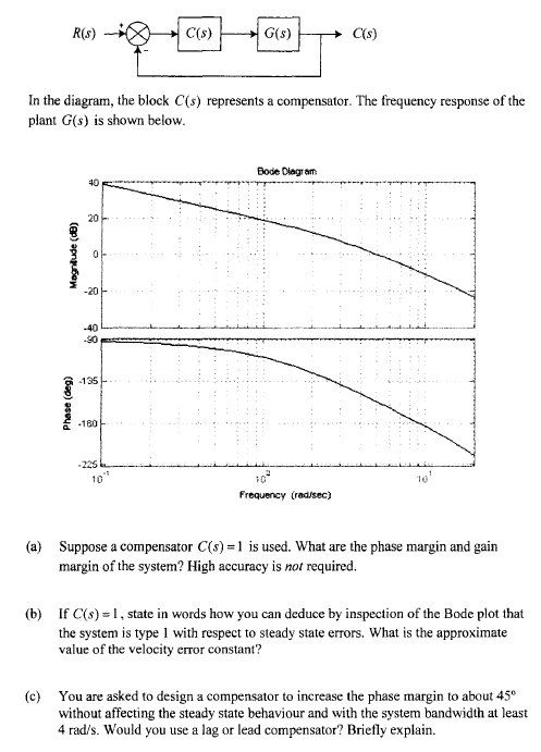
Homework Answers

Add Answer to:
You are asked to design a compensator to increase the phase
margin to about 45degree without...
please show steps 5. GH(s) is a minimum-phase system which has the Bode plot shown below. It is desired to increase the phase margin by 40 degrees and also increase the closed-loop system bandwidth....
 please show steps
5. GH(s) is a minimum-phase system which has the Bode plot shown below. It is desired to increase the phase margin by 40 degrees and also increase the closed-loop system bandwidth. Design a lead compensator for this purpose. Determine (1) the ratio of the pole to the zero, α , (2) the frequency where the maximum phase shift from the compensator should be placed, and then (3) the pole and zero. You need not draw the Bode...
please show steps
5. GH(s) is a minimum-phase system which has the Bode plot shown below. It is desired to increase the phase margin by 40 degrees and also increase the closed-loop system bandwidth. Design a lead compensator for this purpose. Determine (1) the ratio of the pole to the zero, α , (2) the frequency where the maximum phase shift from the compensator should be placed, and then (3) the pole and zero. You need not draw the Bode...
urgent!! II Lag/lead Compensator Design A certain plant with unity feedback has the model given by GP(s) s(1 +0.1s) (1 0.2s) Design a phase-lag OR phase-lead compensator such that: 1. The steady-...
 urgent!!
II Lag/lead Compensator Design A certain plant with unity feedback has the model given by GP(s) s(1 +0.1s) (1 0.2s) Design a phase-lag OR phase-lead compensator such that: 1. The steady- state error with respect to a unit ramp input is no more than 0.01; 2. Phase margin is approximately 40
II Lag/lead Compensator Design A certain plant with unity feedback has the model given by GP(s) s(1 +0.1s) (1 0.2s) Design a phase-lag OR phase-lead compensator such that:...
urgent!!
II Lag/lead Compensator Design A certain plant with unity feedback has the model given by GP(s) s(1 +0.1s) (1 0.2s) Design a phase-lag OR phase-lead compensator such that: 1. The steady- state error with respect to a unit ramp input is no more than 0.01; 2. Phase margin is approximately 40
II Lag/lead Compensator Design A certain plant with unity feedback has the model given by GP(s) s(1 +0.1s) (1 0.2s) Design a phase-lag OR phase-lead compensator such that:...
urgent! II Lead-Lag Controller Design A plant has the open-loop transfer function with unity feedback: 20(s +1) G, (s) s(10s +D(0.1258 +D(0.05s +1)(0.02s +1) Design a phase lag-lead compensator th...
 urgent!
II Lead-Lag Controller Design A plant has the open-loop transfer function with unity feedback: 20(s +1) G, (s) s(10s +D(0.1258 +D(0.05s +1)(0.02s +1) Design a phase lag-lead compensator that satisfies the following specifications must by the compensated system 1. The steady-state error for a unit ramp input must be 0.002; 2. The compensated phase margin must be approximately 48; must be approximately 25 rad/sec.
II Lead-Lag Controller Design A plant has the open-loop transfer function with unity feedback: 20(s...
urgent!
II Lead-Lag Controller Design A plant has the open-loop transfer function with unity feedback: 20(s +1) G, (s) s(10s +D(0.1258 +D(0.05s +1)(0.02s +1) Design a phase lag-lead compensator that satisfies the following specifications must by the compensated system 1. The steady-state error for a unit ramp input must be 0.002; 2. The compensated phase margin must be approximately 48; must be approximately 25 rad/sec.
II Lead-Lag Controller Design A plant has the open-loop transfer function with unity feedback: 20(s...
Prob. 5 (30 pts): You are to design a compensator for a radar antenna as shown...
 Prob. 5 (30 pts): You are to design a compensator for a radar antenna as shown below. Determine G. (s) so that (a)* The closed-loop system has a bandwidth of approximately 20 rad/s. (b) The closed loop system must have positive phase margin. (6) Increase the attenuation at 200 rad/sec or higher. *You can assume that the bandwidth of the closed system is equal to the gain crossover frequency of the open loop system. You may wish to use the...
urgent!! II Lag/lead Compensator Design A certain plant with unity feedback has the model given by...
 urgent!!
II Lag/lead Compensator Design A certain plant with unity feedback has the model given by GP(s) s(1 +0.1s) (1 0.2s) Design a phase-lag OR phase-lead compensator such that: 1. The steady- state error with respect to a unit ramp input is no more than 0.01; 2. Phase margin is approximately 40
urgent!!
II Lag/lead Compensator Design A certain plant with unity feedback has the model given by GP(s) s(1 +0.1s) (1 0.2s) Design a phase-lag OR phase-lead compensator such that: 1. The steady- state error with respect to a unit ramp input is no more than 0.01; 2. Phase margin is approximately 40
Question 2: 5+3+5-13Marks A third-order system having in open loop tansfer finction KG(s) is representative of a ty...
 Question 2: 5+3+5-13Marks A third-order system having in open loop tansfer finction KG(s) is representative of a typical temperature control system. a) Design a lag compensator using bode plot approach to Justify in achieving the desired transient and steady state performance objectives specifically the phase margin should be at least 40 and Kp 9. b) Based on the design (a) construct the Lag compensator using Electrical Network. c) Design a lag compensator using root locus approach and Justify in achieving...
Y(s) C(s) G(s) R(S) Figure 1: Closed-loop system Q2 Consider the setup in Figure 1 with S s1 (i) ...
 Y(s) C(s) G(s) R(S) Figure 1: Closed-loop system Q2 Consider the setup in Figure 1 with S s1 (i) Design a K,τ, α in the lead compensator 1TOS so that the closed-loop system shown in Figure 1 has a steady state error of.0 for a unit ramp reference input at R and a phase margin of about 45 degrees K, α, τ without Bode plots. When you add phase with the lead compensator add an additional 10 degrees of phase....
Write a MATLAB program that w design a PD compensator assuming second-order approximations as fol...
 Write a MATLAB program that w design a PD compensator assuming second-order approximations as follows. . Allow the user to input the desired percent overshoot, peak time and gain required to meet a steady-state error specification Display the gain-compensated Bode plot . Calculate the required phase margin and bandwidth. . Display the pole, zero, and gain of the PD compensator. Display the compensated Bode plot ·Output the step response of the PD-compensated system to test your second-order approximation. [Implement your...
7. Consider the following closed-loop system in which G(s5 Design a lag compensator, Ge( steady-s...
 7. Consider the following closed-loop system in which G(s5 Design a lag compensator, Ge( steady-state error due to a ramp input is 2% of the velocity of the ramp and the phase margin is 45°.
7. Consider the following closed-loop system in which G(s5 Design a lag compensator, Ge( steady-state error due to a ramp input is 2% of the velocity of the ramp and the phase margin is 45°.
7. Consider the following closed-loop system in which G(s5 Design a lag compensator, Ge( steady-state error due to a ramp input is 2% of the velocity of the ramp and the phase margin is 45°.
The transfer function of the given physical system is 2500 Gp(s)-T-1000 Part 3 1. Frequency response (a) Draw the bode...
 The transfer function of the given physical system is 2500 Gp(s)-T-1000 Part 3 1. Frequency response (a) Draw the bode plot of open-loop transfer function when K (b) Use bode plot of open-loop transfer function to determine the type of system (do not use transfer function) (c) For what input the system will have constant steady-state error (d) for the unit input in item (c) calculate the constant steady-state error.(Use bode plot to calculate the error.) (e) Design a lead...
 please show steps
5. GH(s) is a minimum-phase system which has the Bode plot shown below. It is desired to increase the phase margin by 40 degrees and also increase the closed-loop system bandwidth. Design a lead compensator for this purpose. Determine (1) the ratio of the pole to the zero, α , (2) the frequency where the maximum phase shift from the compensator should be placed, and then (3) the pole and zero. You need not draw the Bode...
please show steps
5. GH(s) is a minimum-phase system which has the Bode plot shown below. It is desired to increase the phase margin by 40 degrees and also increase the closed-loop system bandwidth. Design a lead compensator for this purpose. Determine (1) the ratio of the pole to the zero, α , (2) the frequency where the maximum phase shift from the compensator should be placed, and then (3) the pole and zero. You need not draw the Bode...
 urgent!!
II Lag/lead Compensator Design A certain plant with unity feedback has the model given by GP(s) s(1 +0.1s) (1 0.2s) Design a phase-lag OR phase-lead compensator such that: 1. The steady- state error with respect to a unit ramp input is no more than 0.01; 2. Phase margin is approximately 40
II Lag/lead Compensator Design A certain plant with unity feedback has the model given by GP(s) s(1 +0.1s) (1 0.2s) Design a phase-lag OR phase-lead compensator such that:...
urgent!!
II Lag/lead Compensator Design A certain plant with unity feedback has the model given by GP(s) s(1 +0.1s) (1 0.2s) Design a phase-lag OR phase-lead compensator such that: 1. The steady- state error with respect to a unit ramp input is no more than 0.01; 2. Phase margin is approximately 40
II Lag/lead Compensator Design A certain plant with unity feedback has the model given by GP(s) s(1 +0.1s) (1 0.2s) Design a phase-lag OR phase-lead compensator such that:...
 urgent!
II Lead-Lag Controller Design A plant has the open-loop transfer function with unity feedback: 20(s +1) G, (s) s(10s +D(0.1258 +D(0.05s +1)(0.02s +1) Design a phase lag-lead compensator that satisfies the following specifications must by the compensated system 1. The steady-state error for a unit ramp input must be 0.002; 2. The compensated phase margin must be approximately 48; must be approximately 25 rad/sec.
II Lead-Lag Controller Design A plant has the open-loop transfer function with unity feedback: 20(s...
urgent!
II Lead-Lag Controller Design A plant has the open-loop transfer function with unity feedback: 20(s +1) G, (s) s(10s +D(0.1258 +D(0.05s +1)(0.02s +1) Design a phase lag-lead compensator that satisfies the following specifications must by the compensated system 1. The steady-state error for a unit ramp input must be 0.002; 2. The compensated phase margin must be approximately 48; must be approximately 25 rad/sec.
II Lead-Lag Controller Design A plant has the open-loop transfer function with unity feedback: 20(s...
 Prob. 5 (30 pts): You are to design a compensator for a radar antenna as shown below. Determine G. (s) so that (a)* The closed-loop system has a bandwidth of approximately 20 rad/s. (b) The closed loop system must have positive phase margin. (6) Increase the attenuation at 200 rad/sec or higher. *You can assume that the bandwidth of the closed system is equal to the gain crossover frequency of the open loop system. You may wish to use the...
 urgent!!
II Lag/lead Compensator Design A certain plant with unity feedback has the model given by GP(s) s(1 +0.1s) (1 0.2s) Design a phase-lag OR phase-lead compensator such that: 1. The steady- state error with respect to a unit ramp input is no more than 0.01; 2. Phase margin is approximately 40
urgent!!
II Lag/lead Compensator Design A certain plant with unity feedback has the model given by GP(s) s(1 +0.1s) (1 0.2s) Design a phase-lag OR phase-lead compensator such that: 1. The steady- state error with respect to a unit ramp input is no more than 0.01; 2. Phase margin is approximately 40
 Question 2: 5+3+5-13Marks A third-order system having in open loop tansfer finction KG(s) is representative of a typical temperature control system. a) Design a lag compensator using bode plot approach to Justify in achieving the desired transient and steady state performance objectives specifically the phase margin should be at least 40 and Kp 9. b) Based on the design (a) construct the Lag compensator using Electrical Network. c) Design a lag compensator using root locus approach and Justify in achieving...
 Y(s) C(s) G(s) R(S) Figure 1: Closed-loop system Q2 Consider the setup in Figure 1 with S s1 (i) Design a K,τ, α in the lead compensator 1TOS so that the closed-loop system shown in Figure 1 has a steady state error of.0 for a unit ramp reference input at R and a phase margin of about 45 degrees K, α, τ without Bode plots. When you add phase with the lead compensator add an additional 10 degrees of phase....
 Write a MATLAB program that w design a PD compensator assuming second-order approximations as follows. . Allow the user to input the desired percent overshoot, peak time and gain required to meet a steady-state error specification Display the gain-compensated Bode plot . Calculate the required phase margin and bandwidth. . Display the pole, zero, and gain of the PD compensator. Display the compensated Bode plot ·Output the step response of the PD-compensated system to test your second-order approximation. [Implement your...
 7. Consider the following closed-loop system in which G(s5 Design a lag compensator, Ge( steady-state error due to a ramp input is 2% of the velocity of the ramp and the phase margin is 45°.
7. Consider the following closed-loop system in which G(s5 Design a lag compensator, Ge( steady-state error due to a ramp input is 2% of the velocity of the ramp and the phase margin is 45°.
7. Consider the following closed-loop system in which G(s5 Design a lag compensator, Ge( steady-state error due to a ramp input is 2% of the velocity of the ramp and the phase margin is 45°.
 The transfer function of the given physical system is 2500 Gp(s)-T-1000 Part 3 1. Frequency response (a) Draw the bode plot of open-loop transfer function when K (b) Use bode plot of open-loop transfer function to determine the type of system (do not use transfer function) (c) For what input the system will have constant steady-state error (d) for the unit input in item (c) calculate the constant steady-state error.(Use bode plot to calculate the error.) (e) Design a lead...
Most questions answered within 3 hours.
-
Home Corporation will open a new store on January 1. Based on
experience from its other...
asked 2 minutes ago -
In a neoclassical model, use the IS-LM to analyze the effect of
a permanent money supply...
asked 36 minutes ago -
An electron passes through a point 2.67 cm from a long straight
wire as it moves...
asked 1 hour ago -
A grammar is a 4-tuple G, G = (Ν, Σ, Π, Σ, S) where, Ν is...
asked 1 hour ago -
In this part, calculate the present values. Use the Excel PV
function to compute the present...
asked 1 hour ago -
Part 1. Primitive Types, Sorting, Recursion for
Homework.java
a) Implement the static method initializeArray that receives...
asked 3 hours ago -
Using C++, build a sorter that can rank a sequence of numbers in
a descending order....
asked 2 hours ago -
Derive ground state term symbols. Use notation 2S(1/2) for state
2S1/2
a) d5
b) f3
c)...
asked 3 hours ago -
A sample of size 31 will be drawn from a population with mean 39
and standard...
asked 4 hours ago -
What is the effect on the P-value when a test is changed from a
two-tailed hypothesis...
asked 4 hours ago -
I wish to estimate µ, the mean of a population. After I collect
and an-
alyze...
asked 4 hours ago -
At a local university, you poll a group of 115 students and find
that 37 of...
asked 4 hours ago