
Homework Answers


Add Answer to:
Y(s) C(s) G(s) R(S) Figure 1: Closed-loop system Q2 Consider the setup in Figure 1 with S s1 (i) ...
Consider the system shown as below. Draw a Bode diagram of the open-loop transfer function G(s).
 1 Consider the system shown as below. Draw a Bode diagram of the open-loop transfer function G(s). Determine the phase margin, gain-crossover frequency, gain margin and phase-crossover frequency, (Sketch the bode diagram by hand) 2 Consider the system shown as below. Use MATLAB to draw a bode diagram of the open-loop transfer function G(s). Show the gain-crossover frequency and phase-crossover frequency in the Bode diagram and determine the phase margin and gain margin. 3. Consider the system shown as below. Design a...
please show steps 5. GH(s) is a minimum-phase system which has the Bode plot shown below. It is desired to increase the phase margin by 40 degrees and also increase the closed-loop system bandwidth....
 please show steps
5. GH(s) is a minimum-phase system which has the Bode plot shown below. It is desired to increase the phase margin by 40 degrees and also increase the closed-loop system bandwidth. Design a lead compensator for this purpose. Determine (1) the ratio of the pole to the zero, α , (2) the frequency where the maximum phase shift from the compensator should be placed, and then (3) the pole and zero. You need not draw the Bode...
please show steps
5. GH(s) is a minimum-phase system which has the Bode plot shown below. It is desired to increase the phase margin by 40 degrees and also increase the closed-loop system bandwidth. Design a lead compensator for this purpose. Determine (1) the ratio of the pole to the zero, α , (2) the frequency where the maximum phase shift from the compensator should be placed, and then (3) the pole and zero. You need not draw the Bode...
Problem 3 Consider the transfer function: 108 (s2 5s +100) (s + 1000)2 G(s) 1. Sketch...
 Problem 3 Consider the transfer function: 108 (s2 5s +100) (s + 1000)2 G(s) 1. Sketch the bode diagram for G. 2. Knowing that a proportional controller with gain 1000 in a unity feedback loop with G results in an unstable system, what are the phase and gain margins of G? 3. Design a proportional controller that achieves a gain margin of 40dB. gain of 10dB at 0.01rad/s and a gain margin 4. Design that is infinity. compensator that results...
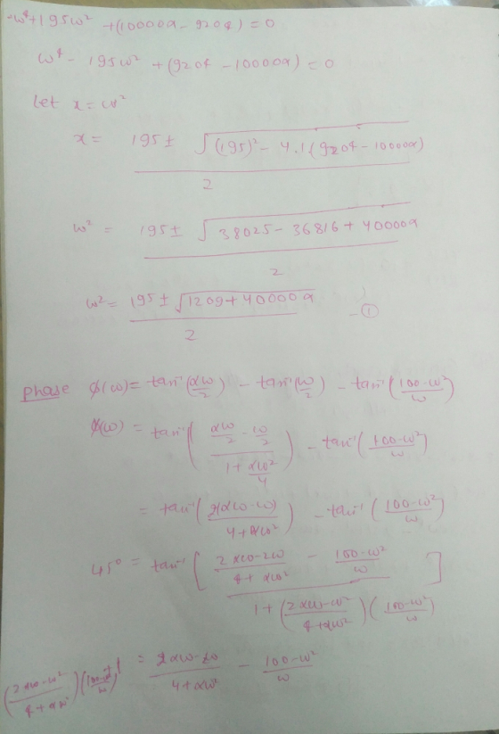
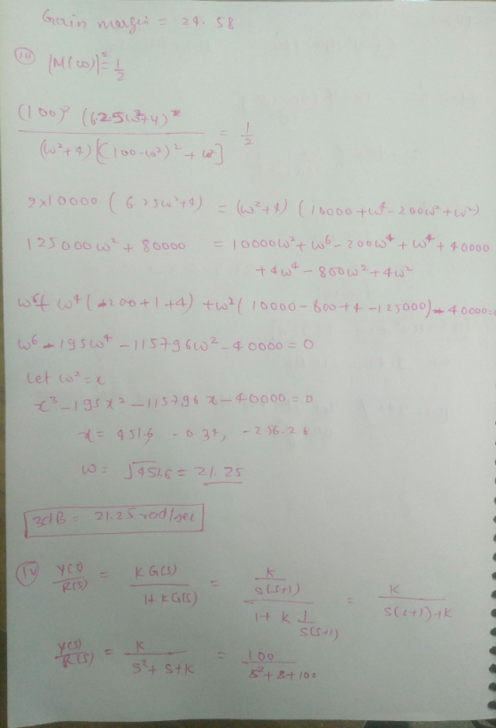
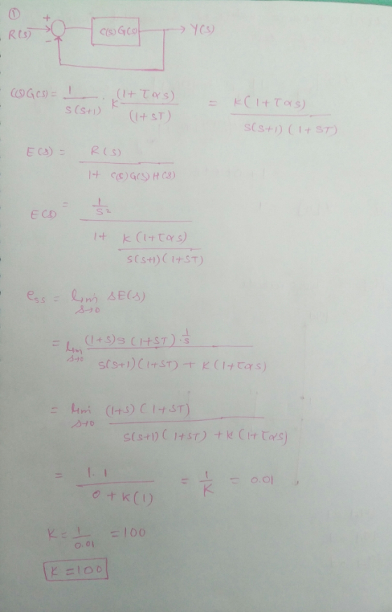
The parameters are as follows k=10 a=0.50 b=0.3 c=0.6 d=9 w_1=12 w_2=15 Kv=30 A feedback control system (illustrated in Figure 1) needs to be designed such that the closed-loop system is asymptotical...
 The parameters are as follows
k=10 a=0.50 b=0.3 c=0.6 d=9 w_1=12 w_2=15
Kv=30
A feedback control system (illustrated in Figure 1) needs to be
designed such that the closed-loop system is asymptotically stable
and such that the following design criteria are met:
the gain crossover frequency wc should be between
w1 and w2.
the steady-state error should be zero in response to a unit
step reference.
the velocity constant should be greater than Kv (in
other words, the steady-state unit...
The parameters are as follows
k=10 a=0.50 b=0.3 c=0.6 d=9 w_1=12 w_2=15
Kv=30
A feedback control system (illustrated in Figure 1) needs to be
designed such that the closed-loop system is asymptotically stable
and such that the following design criteria are met:
the gain crossover frequency wc should be between
w1 and w2.
the steady-state error should be zero in response to a unit
step reference.
the velocity constant should be greater than Kv (in
other words, the steady-state unit...
Consider the unity-feedback system shown below: R(s) E(s) input: r(t), output: y(t) C(s) P(s) error: e()...
 Consider the unity-feedback system shown below: R(s) E(s) input: r(t), output: y(t) C(s) P(s) error: e() r(t) y(t) closed-loop transfer-function: Hyr(sD t the closed-loop transfer-function be Hyr(s) Y (s) R(s) Let the transfer-function of the plant be P(s) 10 s (s 1) (s 5) The open-loop transfer-function is G(s) P(s) C(s) DESIGN OBJECTIVES: Find a controller C(s) such that the following are satisfied i) The closed-loop system is stable. ii) The steady-state error ess due to a unit-ramp input r(t)...
Bode Diagram 10 10 Frequency (rad/s) Bode Diagram 100F 140 10 10 Frequency (rad/s) Figure Q4.2 4. The de servo system s...
 Bode Diagram 10 10 Frequency (rad/s) Bode Diagram 100F 140 10 10 Frequency (rad/s) Figure Q4.2 4. The de servo system shown in Figure Q4.1 is required to have a transient step response speci fication with a peak time of 0.58 seconds or better, and a +2% setting time of 1.7 seconds or better 01(s) K (s)G(s) s(s 1 (s 5) Figure Q4.1 The Bode diagram of the open-loop system is shown in Figure Q4.2 on page 8. This Bode...
Question 3 (10 +10+10+15 45 marks) E(s) C(s) R(s) Figure 3: Unity feedback control system for Question 3 For the unity...
 Question 3 (10 +10+10+15 45 marks) E(s) C(s) R(s) Figure 3: Unity feedback control system for Question 3 For the unity feedback control system shown in Figure 3, 100 G(S) (s+2)(+10) Page 3 of 7 NEE3201 Examination Paper CRICOS Provider No: 00124k a) Determine the phase margin, the gain crossover frequency, the gain margin, the phase crossover frequency of the system when Gc(s)-1, 10 marks) b) Design a proportional controller Gc(s)-K so that a phase margin of 50° is achieved....
Determine the proportioanl gain constant Kp and T such that the bandwidth of the closed-loop system...
 Determine the proportioanl gain constant Kp and T such that the
bandwidth of the closed-loop system is around 0.55 rad/sec and an
overshoot of around 9%. Note that the closed-loop bandwidth is
close to the gain crossover (cut-off) frequency. Check your design
in both frequency and time domain and comment. Determine the
maximum overshoot and settling time. Determine as well, using a
Bode diagram, the expression of the stead state closed loop output
for a sinusodial input with 0 deg...
Determine the proportioanl gain constant Kp and T such that the
bandwidth of the closed-loop system is around 0.55 rad/sec and an
overshoot of around 9%. Note that the closed-loop bandwidth is
close to the gain crossover (cut-off) frequency. Check your design
in both frequency and time domain and comment. Determine the
maximum overshoot and settling time. Determine as well, using a
Bode diagram, the expression of the stead state closed loop output
for a sinusodial input with 0 deg...
Q.4 A position control system is shown in Figure Q4. Assume that K(s) = K, the plant 50 s(0.2s +1) transfer function is given by G(s) s02s y(t) r(t) Figure Q4: Feedback control system. (a) Design a l...
 Q.4 A position control system is shown in Figure Q4. Assume that K(s) = K, the plant 50 s(0.2s +1) transfer function is given by G(s) s02s y(t) r(t) Figure Q4: Feedback control system. (a) Design a lead compensator so that the closed-loop system satisfies the following specifications (i) The steady-state error to a unit-ramp input is less than 1/200 (ii) The unit-step response has an overshoot of less than 16% Ts +1 Hint: Compensator, Dc(s)=aTs+ 1, wm-T (18 marks)...
Figure 1 Problem 3 For the system shown in the above figure, where G(s) a) Draw...
 Figure 1 Problem 3 For the system shown in the above figure, where G(s) a) Draw a Bode diagram of the open-loop transfer function G(s) when K 10. b) On your plot, indicate the crossover frequencies, PM, and GM. Is the closed-loop system stable with K-10? c) Determine the value of K such that the phase margin is 30°. What are the gain margin and the crossover frequencies with this K? Note: You can finish problems 2-3 with the help...
 please show steps
5. GH(s) is a minimum-phase system which has the Bode plot shown below. It is desired to increase the phase margin by 40 degrees and also increase the closed-loop system bandwidth. Design a lead compensator for this purpose. Determine (1) the ratio of the pole to the zero, α , (2) the frequency where the maximum phase shift from the compensator should be placed, and then (3) the pole and zero. You need not draw the Bode...
please show steps
5. GH(s) is a minimum-phase system which has the Bode plot shown below. It is desired to increase the phase margin by 40 degrees and also increase the closed-loop system bandwidth. Design a lead compensator for this purpose. Determine (1) the ratio of the pole to the zero, α , (2) the frequency where the maximum phase shift from the compensator should be placed, and then (3) the pole and zero. You need not draw the Bode...
 Problem 3 Consider the transfer function: 108 (s2 5s +100) (s + 1000)2 G(s) 1. Sketch the bode diagram for G. 2. Knowing that a proportional controller with gain 1000 in a unity feedback loop with G results in an unstable system, what are the phase and gain margins of G? 3. Design a proportional controller that achieves a gain margin of 40dB. gain of 10dB at 0.01rad/s and a gain margin 4. Design that is infinity. compensator that results...
 The parameters are as follows
k=10 a=0.50 b=0.3 c=0.6 d=9 w_1=12 w_2=15
Kv=30
A feedback control system (illustrated in Figure 1) needs to be
designed such that the closed-loop system is asymptotically stable
and such that the following design criteria are met:
the gain crossover frequency wc should be between
w1 and w2.
the steady-state error should be zero in response to a unit
step reference.
the velocity constant should be greater than Kv (in
other words, the steady-state unit...
The parameters are as follows
k=10 a=0.50 b=0.3 c=0.6 d=9 w_1=12 w_2=15
Kv=30
A feedback control system (illustrated in Figure 1) needs to be
designed such that the closed-loop system is asymptotically stable
and such that the following design criteria are met:
the gain crossover frequency wc should be between
w1 and w2.
the steady-state error should be zero in response to a unit
step reference.
the velocity constant should be greater than Kv (in
other words, the steady-state unit...
 Consider the unity-feedback system shown below: R(s) E(s) input: r(t), output: y(t) C(s) P(s) error: e() r(t) y(t) closed-loop transfer-function: Hyr(sD t the closed-loop transfer-function be Hyr(s) Y (s) R(s) Let the transfer-function of the plant be P(s) 10 s (s 1) (s 5) The open-loop transfer-function is G(s) P(s) C(s) DESIGN OBJECTIVES: Find a controller C(s) such that the following are satisfied i) The closed-loop system is stable. ii) The steady-state error ess due to a unit-ramp input r(t)...
 Bode Diagram 10 10 Frequency (rad/s) Bode Diagram 100F 140 10 10 Frequency (rad/s) Figure Q4.2 4. The de servo system shown in Figure Q4.1 is required to have a transient step response speci fication with a peak time of 0.58 seconds or better, and a +2% setting time of 1.7 seconds or better 01(s) K (s)G(s) s(s 1 (s 5) Figure Q4.1 The Bode diagram of the open-loop system is shown in Figure Q4.2 on page 8. This Bode...
 Question 3 (10 +10+10+15 45 marks) E(s) C(s) R(s) Figure 3: Unity feedback control system for Question 3 For the unity feedback control system shown in Figure 3, 100 G(S) (s+2)(+10) Page 3 of 7 NEE3201 Examination Paper CRICOS Provider No: 00124k a) Determine the phase margin, the gain crossover frequency, the gain margin, the phase crossover frequency of the system when Gc(s)-1, 10 marks) b) Design a proportional controller Gc(s)-K so that a phase margin of 50° is achieved....
 Determine the proportioanl gain constant Kp and T such that the
bandwidth of the closed-loop system is around 0.55 rad/sec and an
overshoot of around 9%. Note that the closed-loop bandwidth is
close to the gain crossover (cut-off) frequency. Check your design
in both frequency and time domain and comment. Determine the
maximum overshoot and settling time. Determine as well, using a
Bode diagram, the expression of the stead state closed loop output
for a sinusodial input with 0 deg...
Determine the proportioanl gain constant Kp and T such that the
bandwidth of the closed-loop system is around 0.55 rad/sec and an
overshoot of around 9%. Note that the closed-loop bandwidth is
close to the gain crossover (cut-off) frequency. Check your design
in both frequency and time domain and comment. Determine the
maximum overshoot and settling time. Determine as well, using a
Bode diagram, the expression of the stead state closed loop output
for a sinusodial input with 0 deg...
 Q.4 A position control system is shown in Figure Q4. Assume that K(s) = K, the plant 50 s(0.2s +1) transfer function is given by G(s) s02s y(t) r(t) Figure Q4: Feedback control system. (a) Design a lead compensator so that the closed-loop system satisfies the following specifications (i) The steady-state error to a unit-ramp input is less than 1/200 (ii) The unit-step response has an overshoot of less than 16% Ts +1 Hint: Compensator, Dc(s)=aTs+ 1, wm-T (18 marks)...
 Figure 1 Problem 3 For the system shown in the above figure, where G(s) a) Draw a Bode diagram of the open-loop transfer function G(s) when K 10. b) On your plot, indicate the crossover frequencies, PM, and GM. Is the closed-loop system stable with K-10? c) Determine the value of K such that the phase margin is 30°. What are the gain margin and the crossover frequencies with this K? Note: You can finish problems 2-3 with the help...
Most questions answered within 3 hours.
-
1.How large must the coefficient of static friction be between
the tires and the road if...
asked 9 minutes ago -
What is the time complexity (Big-O) of the following code?
class Main
{
// Recursive...
asked 9 minutes ago -
Economists look at any situation in terms of its component
parts: the people making decisions, the...
asked 15 minutes ago -
What is a population?
Select one:
a. All of the individual organisms belonging to the same...
asked 19 minutes ago -
You have a yeast cell culture with a concentration of 5x10^4
cells/ml. If you dilute this...
asked 23 minutes ago -
In which direction the Reaction goes? Show detailed process.
SeO3 + 2ClO2. + 2H3O <---> Se...
asked 36 minutes ago -
Unexposed silver halides are removed from photographic film when
they react with sodium thiosulfate
(Na2S2O3, called...
asked 37 minutes ago -
A 0.3054 gram sample of the mineral chalcopyrite (CuFeS2)
yielded 0.6525 gram BaSO4 precipitate. What is...
asked 37 minutes ago -
An short-seller in Tesla is worried the latest management
earnings forecast is too aggressive and the...
asked 1 hour ago -
Question 3 (1 point)
Fill in the blank. Speed Car Rental company found that the tire...
asked 1 hour ago -
1. A copper wire is 26.61 cm long and weighs 1.265 g. The
density of copper...
asked 1 hour ago -
Remember that a concept sketch consists of a sketch (or
series of sketches), labels, and complete...
asked 1 hour ago