The parameters are as follows
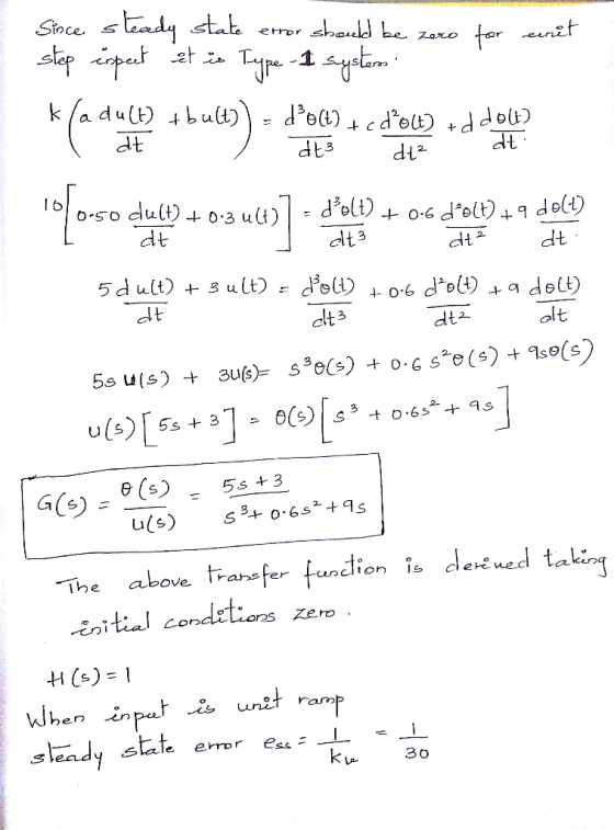
k=10 a=0.50 b=0.3 c=0.6 d=9 w_1=12 w_2=15 Kv=30
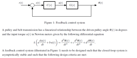
A feedback control system (illustrated in Figure 1) needs to be designed such that the closed-loop system is asymptotically stable and such that the following design criteria are met:
- the gain crossover frequency wc should be between w1 and w2.
- the steady-state error should be zero in response to a unit step reference.
- the velocity constant should be greater than Kv (in other words, the steady-state unit ramp error should be less than 1=Kv).
- the phase margin should be at least 55o.
If the four performance criteria are met, further iteration of the controller may be undertaken (if you wish) to minimise the settling time of the step response from r(t) to y(t). If you cannot meet any of the design criteria, get as close as you can while ensuring closed-loop stability, and explain where and why compromises were needed.
This task will be approached incrementally, beginning with a proportional controller and finishing with a lead-lag controller.
All graphs should be clearly labelled and legible, and all
design steps
should include some justification. MATLAB or a similar
computational package may be used for any of the
calculations or graphs requiqired
Consider a phase-lead compensator ts +1 Show that this controller cannot satisfy all of the design requirements (hint: select Kp to satisfy the velocity constant requirement and show that the conditions to apply the inversion formulae do not hold). Find parameters for a phase-lead compensator that satisfies the constraints on the gain crossover frequency and on the phase margin (crieria 1 and 2), while keeping the velocity error as small as possible. Draw the bode plot of the resulting system, showing the required phase margin, and plot the closed-loop response to a unit step input. Plot the tracking error in response to a unit ramp, and show that the velocity error requirement rion 3) is not met.
Homework Answers

Add Answer to:
The parameters are as follows k=10 a=0.50 b=0.3 c=0.6 d=9 w_1=12 w_2=15 Kv=30 A feedback control system (illustrated in Figure 1) needs to be designed such that the closed-loop system is asymptotical...
The parameters are as follows k=10 a=0.50 b=0.3 c=0.6 d=9 w_1=12 w_2=15 Kv=30 A feedback control system (illustrated in Figure 1) needs to be designed such that the closed-loop system is asymptotical...
 The parameters are as follows
k=10 a=0.50 b=0.3 c=0.6 d=9 w_1=12 w_2=15
Kv=30
A feedback control system
(illustrated in Figure 1) needs to be designed such that the
closed-loop system is asymptotically stable and such that the
following design criteria are met:
the gain crossover frequency wc should be between
w1 and w2.
the steady-state error should be zero in response to a unit
step reference.
the velocity constant should be greater than Kv (in
other words, the steady-state unit...
The parameters are as follows
k=10 a=0.50 b=0.3 c=0.6 d=9 w_1=12 w_2=15
Kv=30
A feedback control system
(illustrated in Figure 1) needs to be designed such that the
closed-loop system is asymptotically stable and such that the
following design criteria are met:
the gain crossover frequency wc should be between
w1 and w2.
the steady-state error should be zero in response to a unit
step reference.
the velocity constant should be greater than Kv (in
other words, the steady-state unit...
The parameters are as follows k=0.1,a=1.00,b=1,c=1.0,d=25,w_1=20,w_2=25,Kv=50 e(t) r(t) e (t) G(s) Figure 1: Feedback...
 The parameters are as follows
k=0.1,a=1.00,b=1,c=1.0,d=25,w_1=20,w_2=25,Kv=50
e(t) r(t) e (t) G(s) Figure 1: Feedback control system A pulley and belt transmission has a linearized relationship between the driven pulley angle e (t) in degrees and the input torque u(t) in Newton meters given by the following differential equation du(t) dt A feedback control system (illustrated in Figure 1) needs to be designed such that the closed-loop system is asymptotically stable and such that the following design criteria are met 1....
The parameters are as follows
k=0.1,a=1.00,b=1,c=1.0,d=25,w_1=20,w_2=25,Kv=50
e(t) r(t) e (t) G(s) Figure 1: Feedback control system A pulley and belt transmission has a linearized relationship between the driven pulley angle e (t) in degrees and the input torque u(t) in Newton meters given by the following differential equation du(t) dt A feedback control system (illustrated in Figure 1) needs to be designed such that the closed-loop system is asymptotically stable and such that the following design criteria are met 1....
G) r(t) Figure 1: Feedback control system A pulley and belt transmission has a linearized relationship between the driven pulley angle θ(t) in degrees and the input torque u(t) in Newton meters given...
 G) r(t) Figure 1: Feedback control system A pulley and belt transmission has a linearized relationship between the driven pulley angle θ(t) in degrees and the input torque u(t) in Newton meters given by the following differential equation du(t) A feedback control system (illustrated in Figure 1) needs to be designed such that the closed-loop system is asymptotically stable and such that the following design criteria are met: 1. the gain crossover frequency a should be between and a 2....
Question 3 (10 +10+10+15 45 marks) E(s) C(s) R(s) Figure 3: Unity feedback control system for Question 3 For the unity...
 Question 3 (10 +10+10+15 45 marks) E(s) C(s) R(s) Figure 3: Unity feedback control system for Question 3 For the unity feedback control system shown in Figure 3, 100 G(S) (s+2)(+10) Page 3 of 7 NEE3201 Examination Paper CRICOS Provider No: 00124k a) Determine the phase margin, the gain crossover frequency, the gain margin, the phase crossover frequency of the system when Gc(s)-1, 10 marks) b) Design a proportional controller Gc(s)-K so that a phase margin of 50° is achieved....
Consider the system shown as below. Draw a Bode diagram of the open-loop transfer function G(s).
 1 Consider the system shown as below. Draw a Bode diagram of the open-loop transfer function G(s). Determine the phase margin, gain-crossover frequency, gain margin and phase-crossover frequency, (Sketch the bode diagram by hand) 2 Consider the system shown as below. Use MATLAB to draw a bode diagram of the open-loop transfer function G(s). Show the gain-crossover frequency and phase-crossover frequency in the Bode diagram and determine the phase margin and gain margin. 3. Consider the system shown as below. Design a...
Q.4 A position control system is shown in Figure Q4. Assume that K(s) = K, the plant 50 s(0.2s +1) transfer function is given by G(s) s02s y(t) r(t) Figure Q4: Feedback control system. (a) Design a l...
 Q.4 A position control system is shown in Figure Q4. Assume that K(s) = K, the plant 50 s(0.2s +1) transfer function is given by G(s) s02s y(t) r(t) Figure Q4: Feedback control system. (a) Design a lead compensator so that the closed-loop system satisfies the following specifications (i) The steady-state error to a unit-ramp input is less than 1/200 (ii) The unit-step response has an overshoot of less than 16% Ts +1 Hint: Compensator, Dc(s)=aTs+ 1, wm-T (18 marks)...
4. Referring to the closed-loop system shown as below, design a lead compensator Ge(s) such that...
 4. Referring to the closed-loop system shown as below, design a lead compensator Ge(s) such that the phase-margin is 45o, gain margin is not less than 8dB, and the static velocity error constant Ky is 4.0 sec1. Plot unit-step and unit-ramp response curves of the compensated system with MATLAB.
Spring 2019 3. Given a closed-loop control system with unity feedback is shown in the block...
 Spring 2019 3. Given a closed-loop control system with unity feedback is shown in the block diagram. G(s) is the open-loop transfer function, and the controller is a gain, K. 1. (20) Calculate the open-loop transfer function tar →Q--t G(s) (10) Calculate the steady-state error to a step input of the open-loop system. 7. (in Bode Form) from the Bode plot. (10) Calculate the shortest possible settling time with a percentage overshoot of 5% or less. 8. 2. (10)Plot the...
A unity feedback closed loop control system is displayed in Figure 4. (a) Assume that the control...
 Please solve as a MATLAB code.
A unity feedback closed loop control system is displayed in Figure 4. (a) Assume that the controller is given by G (s) 2. Based on the lsim function of MATLAB, calculate and obtain the graph of the response for (t) at. Here a 0.5°/s. Find the height error after 10 seconds, (b) In order to reduce the steady-state error, substitute G (s) with the following controller This is a Proportional-Integral (PI) controller. Repeat part...
Please solve as a MATLAB code.
A unity feedback closed loop control system is displayed in Figure 4. (a) Assume that the controller is given by G (s) 2. Based on the lsim function of MATLAB, calculate and obtain the graph of the response for (t) at. Here a 0.5°/s. Find the height error after 10 seconds, (b) In order to reduce the steady-state error, substitute G (s) with the following controller This is a Proportional-Integral (PI) controller. Repeat part...
Problem 30 (15 points) Consider the closed-loop sampled-data system in Figure 6 that uses a sample...
 Problem 30 (15 points) Consider the closed-loop sampled-data system in Figure 6 that uses a sample period of 600 ms. The pulse transfer function of the continuous-time plant is Ge)- 0.04147 z-0.7408 while Ge(2) is the transfer function of a discrete-time compensator. E(Z)G.(2) Figure 6: Closed-loop sampled-data system with compensator Ge() I. (5 points) Is it possible to achieve a steady-sate error ess- 0.05 for a unit-step input r(k) = uo(k) using proportional feedback Ga(z) = K? If yes, derive...
 The parameters are as follows
k=10 a=0.50 b=0.3 c=0.6 d=9 w_1=12 w_2=15
Kv=30
A feedback control system
(illustrated in Figure 1) needs to be designed such that the
closed-loop system is asymptotically stable and such that the
following design criteria are met:
the gain crossover frequency wc should be between
w1 and w2.
the steady-state error should be zero in response to a unit
step reference.
the velocity constant should be greater than Kv (in
other words, the steady-state unit...
The parameters are as follows
k=10 a=0.50 b=0.3 c=0.6 d=9 w_1=12 w_2=15
Kv=30
A feedback control system
(illustrated in Figure 1) needs to be designed such that the
closed-loop system is asymptotically stable and such that the
following design criteria are met:
the gain crossover frequency wc should be between
w1 and w2.
the steady-state error should be zero in response to a unit
step reference.
the velocity constant should be greater than Kv (in
other words, the steady-state unit...
 The parameters are as follows
k=0.1,a=1.00,b=1,c=1.0,d=25,w_1=20,w_2=25,Kv=50
e(t) r(t) e (t) G(s) Figure 1: Feedback control system A pulley and belt transmission has a linearized relationship between the driven pulley angle e (t) in degrees and the input torque u(t) in Newton meters given by the following differential equation du(t) dt A feedback control system (illustrated in Figure 1) needs to be designed such that the closed-loop system is asymptotically stable and such that the following design criteria are met 1....
The parameters are as follows
k=0.1,a=1.00,b=1,c=1.0,d=25,w_1=20,w_2=25,Kv=50
e(t) r(t) e (t) G(s) Figure 1: Feedback control system A pulley and belt transmission has a linearized relationship between the driven pulley angle e (t) in degrees and the input torque u(t) in Newton meters given by the following differential equation du(t) dt A feedback control system (illustrated in Figure 1) needs to be designed such that the closed-loop system is asymptotically stable and such that the following design criteria are met 1....
 G) r(t) Figure 1: Feedback control system A pulley and belt transmission has a linearized relationship between the driven pulley angle θ(t) in degrees and the input torque u(t) in Newton meters given by the following differential equation du(t) A feedback control system (illustrated in Figure 1) needs to be designed such that the closed-loop system is asymptotically stable and such that the following design criteria are met: 1. the gain crossover frequency a should be between and a 2....
 Question 3 (10 +10+10+15 45 marks) E(s) C(s) R(s) Figure 3: Unity feedback control system for Question 3 For the unity feedback control system shown in Figure 3, 100 G(S) (s+2)(+10) Page 3 of 7 NEE3201 Examination Paper CRICOS Provider No: 00124k a) Determine the phase margin, the gain crossover frequency, the gain margin, the phase crossover frequency of the system when Gc(s)-1, 10 marks) b) Design a proportional controller Gc(s)-K so that a phase margin of 50° is achieved....
 Q.4 A position control system is shown in Figure Q4. Assume that K(s) = K, the plant 50 s(0.2s +1) transfer function is given by G(s) s02s y(t) r(t) Figure Q4: Feedback control system. (a) Design a lead compensator so that the closed-loop system satisfies the following specifications (i) The steady-state error to a unit-ramp input is less than 1/200 (ii) The unit-step response has an overshoot of less than 16% Ts +1 Hint: Compensator, Dc(s)=aTs+ 1, wm-T (18 marks)...
 4. Referring to the closed-loop system shown as below, design a lead compensator Ge(s) such that the phase-margin is 45o, gain margin is not less than 8dB, and the static velocity error constant Ky is 4.0 sec1. Plot unit-step and unit-ramp response curves of the compensated system with MATLAB.
 Spring 2019 3. Given a closed-loop control system with unity feedback is shown in the block diagram. G(s) is the open-loop transfer function, and the controller is a gain, K. 1. (20) Calculate the open-loop transfer function tar →Q--t G(s) (10) Calculate the steady-state error to a step input of the open-loop system. 7. (in Bode Form) from the Bode plot. (10) Calculate the shortest possible settling time with a percentage overshoot of 5% or less. 8. 2. (10)Plot the...
 Please solve as a MATLAB code.
A unity feedback closed loop control system is displayed in Figure 4. (a) Assume that the controller is given by G (s) 2. Based on the lsim function of MATLAB, calculate and obtain the graph of the response for (t) at. Here a 0.5°/s. Find the height error after 10 seconds, (b) In order to reduce the steady-state error, substitute G (s) with the following controller This is a Proportional-Integral (PI) controller. Repeat part...
Please solve as a MATLAB code.
A unity feedback closed loop control system is displayed in Figure 4. (a) Assume that the controller is given by G (s) 2. Based on the lsim function of MATLAB, calculate and obtain the graph of the response for (t) at. Here a 0.5°/s. Find the height error after 10 seconds, (b) In order to reduce the steady-state error, substitute G (s) with the following controller This is a Proportional-Integral (PI) controller. Repeat part...
 Problem 30 (15 points) Consider the closed-loop sampled-data system in Figure 6 that uses a sample period of 600 ms. The pulse transfer function of the continuous-time plant is Ge)- 0.04147 z-0.7408 while Ge(2) is the transfer function of a discrete-time compensator. E(Z)G.(2) Figure 6: Closed-loop sampled-data system with compensator Ge() I. (5 points) Is it possible to achieve a steady-sate error ess- 0.05 for a unit-step input r(k) = uo(k) using proportional feedback Ga(z) = K? If yes, derive...
Most questions answered within 3 hours.
-
Consider the reaction, C3 H8 + O2 --> CO2 + H2O. How many
moles of O2...
asked 1 hour ago -
You and your opponent both roll a fair die. If you both roll the
same number,...
asked 1 hour ago -
In a study of the accuracy of fast food drive-through orders,
Restaurant A had 257 accurate...
asked 1 hour ago -
Identify and describe in detail the four categories of
institutions that could be included in a...
asked 1 hour ago -
In python
class Customer:
def __init__(self, customer_id, last_name, first_name, phone_number, address):
self._customer_id = int(customer_id)
self._last_name =...
asked 1 hour ago -
What is an example of a limitation in implementing a new
ERP system and how it...
asked 1 hour ago -
In a section of 9.7cm of an artery with a radius of 2.6mm there
is a...
asked 1 hour ago -
the two carboxylic acid groups of aspartic acid have different
acidities with pKa values of 2.1...
asked 1 hour ago -
Would CuCO3 aqueous salt combined with calcium chloride
form a solid precipitate? If so, what would...
asked 1 hour ago -
How do ECM Solutions assist in embedding a culture of continuous
improvement in an organization? (Project...
asked 1 hour ago -
Directions
These directions introduce the idea of Essential Questions.
Since this may be a new concept...
asked 1 hour ago -
1.b. Fiscal policy is said to suffer from ‘crowding out’.
Explain what this means and why...
asked 2 hours ago