
Homework Answers


(2) Step response:
clc;
clear all;
close all;
num=[4];
den=[0.1 1.1 1 0];
sys=tf(num, den);
step(sys)
(3) Ramp response:
clc;
clear all;
close all;
num=[4];
den=[0.1 1.1 1 0];
sys=tf(num, den);
x=feedback(sys, 1);
t=0:0.01:5;
lsim(x,t,t)
Add Answer to:
4. Referring to the closed-loop system shown as below, design a lead compensator Ge(s) such that...
Consider the system shown as below. Draw a Bode diagram of the open-loop transfer function G(s).
 1 Consider the system shown as below. Draw a Bode diagram of the open-loop transfer function G(s). Determine the phase margin, gain-crossover frequency, gain margin and phase-crossover frequency, (Sketch the bode diagram by hand) 2 Consider the system shown as below. Use MATLAB to draw a bode diagram of the open-loop transfer function G(s). Show the gain-crossover frequency and phase-crossover frequency in the Bode diagram and determine the phase margin and gain margin. 3. Consider the system shown as below. Design a...
7. Consider the following closed-loop system in which G(s5 Design a lag compensator, Ge( steady-s...
 7. Consider the following closed-loop system in which G(s5 Design a lag compensator, Ge( steady-state error due to a ramp input is 2% of the velocity of the ramp and the phase margin is 45°.
7. Consider the following closed-loop system in which G(s5 Design a lag compensator, Ge( steady-state error due to a ramp input is 2% of the velocity of the ramp and the phase margin is 45°.
7. Consider the following closed-loop system in which G(s5 Design a lag compensator, Ge( steady-state error due to a ramp input is 2% of the velocity of the ramp and the phase margin is 45°.
Consider the automobile cruise-control system shown below: Engine ActuatorCarburetor 0.833 and load 40 3s +1 Compensator R(s)E(s) Ge(s) s +1 -t e(t) Sensor 0.03 1) Derive the closed-loop transfer fun...
 Consider the automobile cruise-control system shown below: Engine ActuatorCarburetor 0.833 and load 40 3s +1 Compensator R(s)E(s) Ge(s) s +1 -t e(t) Sensor 0.03 1) Derive the closed-loop transfer function of V(s)/R(s) when Gc(s)-1 2) Derive the closed-loop transfer function of E(s)/R(s) when Ge(s)-1 3) Plot the time history of the error e(t) of the closed-loop system when r(t) is a unit step input. 4) Plot the root-loci of the uncompensated system (when Gc(s)-1). Mark the closed-loop complex poles on...
urgent! II Lead-Lag Controller Design A plant has the open-loop transfer function with unity feedback: 20(s +1) G, (s) s(10s +D(0.1258 +D(0.05s +1)(0.02s +1) Design a phase lag-lead compensator th...
 urgent!
II Lead-Lag Controller Design A plant has the open-loop transfer function with unity feedback: 20(s +1) G, (s) s(10s +D(0.1258 +D(0.05s +1)(0.02s +1) Design a phase lag-lead compensator that satisfies the following specifications must by the compensated system 1. The steady-state error for a unit ramp input must be 0.002; 2. The compensated phase margin must be approximately 48; must be approximately 25 rad/sec.
II Lead-Lag Controller Design A plant has the open-loop transfer function with unity feedback: 20(s...
urgent!
II Lead-Lag Controller Design A plant has the open-loop transfer function with unity feedback: 20(s +1) G, (s) s(10s +D(0.1258 +D(0.05s +1)(0.02s +1) Design a phase lag-lead compensator that satisfies the following specifications must by the compensated system 1. The steady-state error for a unit ramp input must be 0.002; 2. The compensated phase margin must be approximately 48; must be approximately 25 rad/sec.
II Lead-Lag Controller Design A plant has the open-loop transfer function with unity feedback: 20(s...
design a lead compensator For the system with the following open loop transfer function, G(S) (05s+1 Design a lead c...
 design a lead compensator
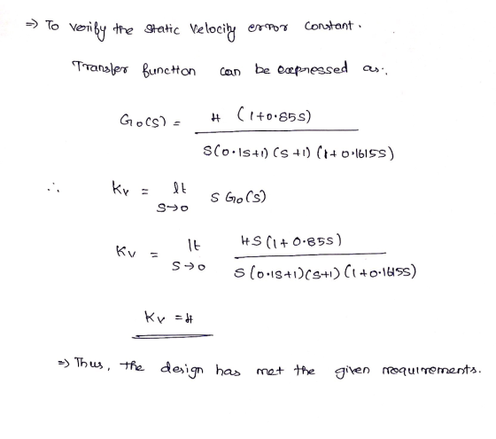
For the system with the following open loop transfer function, G(S) (05s+1 Design a lead compensator so that the velocity error constant 20 sec and the phase margin is at least 50°
For the system with the following open loop transfer function, G(S) (05s+1 Design a lead compensator so that the velocity error constant 20 sec and the phase margin is at least 50°
design a lead compensator
For the system with the following open loop transfer function, G(S) (05s+1 Design a lead compensator so that the velocity error constant 20 sec and the phase margin is at least 50°
For the system with the following open loop transfer function, G(S) (05s+1 Design a lead compensator so that the velocity error constant 20 sec and the phase margin is at least 50°
The parameters are as follows k=10 a=0.50 b=0.3 c=0.6 d=9 w_1=12 w_2=15 Kv=30 A feedback control system (illustrated in Figure 1) needs to be designed such that the closed-loop system is asymptotical...
 The parameters are as follows
k=10 a=0.50 b=0.3 c=0.6 d=9 w_1=12 w_2=15
Kv=30
A feedback control system (illustrated in Figure 1) needs to be
designed such that the closed-loop system is asymptotically stable
and such that the following design criteria are met:
the gain crossover frequency wc should be between
w1 and w2.
the steady-state error should be zero in response to a unit
step reference.
the velocity constant should be greater than Kv (in
other words, the steady-state unit...
The parameters are as follows
k=10 a=0.50 b=0.3 c=0.6 d=9 w_1=12 w_2=15
Kv=30
A feedback control system (illustrated in Figure 1) needs to be
designed such that the closed-loop system is asymptotically stable
and such that the following design criteria are met:
the gain crossover frequency wc should be between
w1 and w2.
the steady-state error should be zero in response to a unit
step reference.
the velocity constant should be greater than Kv (in
other words, the steady-state unit...
Write a MATLAB program that w design a PD compensator assuming second-order approximations as fol...
 Write a MATLAB program that w design a PD compensator assuming second-order approximations as follows. . Allow the user to input the desired percent overshoot, peak time and gain required to meet a steady-state error specification Display the gain-compensated Bode plot . Calculate the required phase margin and bandwidth. . Display the pole, zero, and gain of the PD compensator. Display the compensated Bode plot ·Output the step response of the PD-compensated system to test your second-order approximation. [Implement your...
Y(s) C(s) G(s) R(S) Figure 1: Closed-loop system Q2 Consider the setup in Figure 1 with S s1 (i) ...
 Y(s) C(s) G(s) R(S) Figure 1: Closed-loop system Q2 Consider the setup in Figure 1 with S s1 (i) Design a K,τ, α in the lead compensator 1TOS so that the closed-loop system shown in Figure 1 has a steady state error of.0 for a unit ramp reference input at R and a phase margin of about 45 degrees K, α, τ without Bode plots. When you add phase with the lead compensator add an additional 10 degrees of phase....
2. For the system that has the loop gain transfer function shown, design a compensator that...
 2. For the system that has the loop gain transfer function shown, design a compensator that will improve the steady-state error to a unit ramp input by a factor of exactly 50 for a unity feedback system 30 G(8) s(s+1)(8 +3X8 +5) Validate your design, showing the responses using MATLAB
Bode Diagram 10 10 Frequency (rad/s) Bode Diagram 100F 140 10 10 Frequency (rad/s) Figure Q4.2 4. The de servo system s...
 Bode Diagram 10 10 Frequency (rad/s) Bode Diagram 100F 140 10 10 Frequency (rad/s) Figure Q4.2 4. The de servo system shown in Figure Q4.1 is required to have a transient step response speci fication with a peak time of 0.58 seconds or better, and a +2% setting time of 1.7 seconds or better 01(s) K (s)G(s) s(s 1 (s 5) Figure Q4.1 The Bode diagram of the open-loop system is shown in Figure Q4.2 on page 8. This Bode...
 7. Consider the following closed-loop system in which G(s5 Design a lag compensator, Ge( steady-state error due to a ramp input is 2% of the velocity of the ramp and the phase margin is 45°.
7. Consider the following closed-loop system in which G(s5 Design a lag compensator, Ge( steady-state error due to a ramp input is 2% of the velocity of the ramp and the phase margin is 45°.
7. Consider the following closed-loop system in which G(s5 Design a lag compensator, Ge( steady-state error due to a ramp input is 2% of the velocity of the ramp and the phase margin is 45°.
 Consider the automobile cruise-control system shown below: Engine ActuatorCarburetor 0.833 and load 40 3s +1 Compensator R(s)E(s) Ge(s) s +1 -t e(t) Sensor 0.03 1) Derive the closed-loop transfer function of V(s)/R(s) when Gc(s)-1 2) Derive the closed-loop transfer function of E(s)/R(s) when Ge(s)-1 3) Plot the time history of the error e(t) of the closed-loop system when r(t) is a unit step input. 4) Plot the root-loci of the uncompensated system (when Gc(s)-1). Mark the closed-loop complex poles on...
 urgent!
II Lead-Lag Controller Design A plant has the open-loop transfer function with unity feedback: 20(s +1) G, (s) s(10s +D(0.1258 +D(0.05s +1)(0.02s +1) Design a phase lag-lead compensator that satisfies the following specifications must by the compensated system 1. The steady-state error for a unit ramp input must be 0.002; 2. The compensated phase margin must be approximately 48; must be approximately 25 rad/sec.
II Lead-Lag Controller Design A plant has the open-loop transfer function with unity feedback: 20(s...
urgent!
II Lead-Lag Controller Design A plant has the open-loop transfer function with unity feedback: 20(s +1) G, (s) s(10s +D(0.1258 +D(0.05s +1)(0.02s +1) Design a phase lag-lead compensator that satisfies the following specifications must by the compensated system 1. The steady-state error for a unit ramp input must be 0.002; 2. The compensated phase margin must be approximately 48; must be approximately 25 rad/sec.
II Lead-Lag Controller Design A plant has the open-loop transfer function with unity feedback: 20(s...
 design a lead compensator
For the system with the following open loop transfer function, G(S) (05s+1 Design a lead compensator so that the velocity error constant 20 sec and the phase margin is at least 50°
For the system with the following open loop transfer function, G(S) (05s+1 Design a lead compensator so that the velocity error constant 20 sec and the phase margin is at least 50°
design a lead compensator
For the system with the following open loop transfer function, G(S) (05s+1 Design a lead compensator so that the velocity error constant 20 sec and the phase margin is at least 50°
For the system with the following open loop transfer function, G(S) (05s+1 Design a lead compensator so that the velocity error constant 20 sec and the phase margin is at least 50°
 The parameters are as follows
k=10 a=0.50 b=0.3 c=0.6 d=9 w_1=12 w_2=15
Kv=30
A feedback control system (illustrated in Figure 1) needs to be
designed such that the closed-loop system is asymptotically stable
and such that the following design criteria are met:
the gain crossover frequency wc should be between
w1 and w2.
the steady-state error should be zero in response to a unit
step reference.
the velocity constant should be greater than Kv (in
other words, the steady-state unit...
The parameters are as follows
k=10 a=0.50 b=0.3 c=0.6 d=9 w_1=12 w_2=15
Kv=30
A feedback control system (illustrated in Figure 1) needs to be
designed such that the closed-loop system is asymptotically stable
and such that the following design criteria are met:
the gain crossover frequency wc should be between
w1 and w2.
the steady-state error should be zero in response to a unit
step reference.
the velocity constant should be greater than Kv (in
other words, the steady-state unit...
 Write a MATLAB program that w design a PD compensator assuming second-order approximations as follows. . Allow the user to input the desired percent overshoot, peak time and gain required to meet a steady-state error specification Display the gain-compensated Bode plot . Calculate the required phase margin and bandwidth. . Display the pole, zero, and gain of the PD compensator. Display the compensated Bode plot ·Output the step response of the PD-compensated system to test your second-order approximation. [Implement your...
 Y(s) C(s) G(s) R(S) Figure 1: Closed-loop system Q2 Consider the setup in Figure 1 with S s1 (i) Design a K,τ, α in the lead compensator 1TOS so that the closed-loop system shown in Figure 1 has a steady state error of.0 for a unit ramp reference input at R and a phase margin of about 45 degrees K, α, τ without Bode plots. When you add phase with the lead compensator add an additional 10 degrees of phase....
 2. For the system that has the loop gain transfer function shown, design a compensator that will improve the steady-state error to a unit ramp input by a factor of exactly 50 for a unity feedback system 30 G(8) s(s+1)(8 +3X8 +5) Validate your design, showing the responses using MATLAB
 Bode Diagram 10 10 Frequency (rad/s) Bode Diagram 100F 140 10 10 Frequency (rad/s) Figure Q4.2 4. The de servo system shown in Figure Q4.1 is required to have a transient step response speci fication with a peak time of 0.58 seconds or better, and a +2% setting time of 1.7 seconds or better 01(s) K (s)G(s) s(s 1 (s 5) Figure Q4.1 The Bode diagram of the open-loop system is shown in Figure Q4.2 on page 8. This Bode...
Most questions answered within 3 hours.
-
Which food law was passed in 1996 and changed how pesticide
residues on food were regulated...
asked 15 minutes ago -
companies either hire outside programmers to
write_____ software or use their own internal developers.
asked 14 minutes ago -
A magnetic dipole m(t) = m_0*cos(ωt) can be
described as current density j(r,t) = −cm(t) ×...
asked 14 minutes ago -
Probabilities and Counting. Yahtzee is a game that involves six
fair dice. When rolling all six...
asked 15 minutes ago -
What percent of revenue does net income represent for each
year?
Total Revenue
2017 = 60,319,000...
asked 37 minutes ago -
For Ti+2 (Z=22). Determine the correct ground state
& # of microstates. Use the correct tanabe...
asked 40 minutes ago -
Why did so many investment banks have to start buying CDO’s and
other mortgaged backed securities...
asked 56 minutes ago -
The mean cost of domestic airfares in the United States rose to
an all-time high of...
asked 1 hour ago -
1.Magazine Luiza is a Brazilian retail chain for consumer
electronics. The company currently has 100 stores...
asked 1 hour ago -
What is the molarity of ZnCl2 that forms when 25.0 g of zinc
completely reacts with...
asked 1 hour ago -
For independent X and Y, we have probability density function
for them where pdf of X...
asked 1 hour ago -
The decomposition of SO2Cl2 is first order in SO2Cl2 and has a
rate constant of 1.42...
asked 1 hour ago