 urgent!
Homework Answers

Thank you.
Add Answer to:
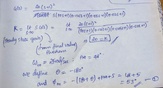
urgent! II Lead-Lag Controller Design A plant has the open-loop transfer function with unity feedback: 20(s +1) G, (s) s(10s +D(0.1258 +D(0.05s +1)(0.02s +1) Design a phase lag-lead compensator th...
urgent!! II Lag/lead Compensator Design A certain plant with unity feedback has the model given by GP(s) s(1 +0.1s) (1 0.2s) Design a phase-lag OR phase-lead compensator such that: 1. The steady-...
 urgent!!
II Lag/lead Compensator Design A certain plant with unity feedback has the model given by GP(s) s(1 +0.1s) (1 0.2s) Design a phase-lag OR phase-lead compensator such that: 1. The steady- state error with respect to a unit ramp input is no more than 0.01; 2. Phase margin is approximately 40
II Lag/lead Compensator Design A certain plant with unity feedback has the model given by GP(s) s(1 +0.1s) (1 0.2s) Design a phase-lag OR phase-lead compensator such that:...
urgent!!
II Lag/lead Compensator Design A certain plant with unity feedback has the model given by GP(s) s(1 +0.1s) (1 0.2s) Design a phase-lag OR phase-lead compensator such that: 1. The steady- state error with respect to a unit ramp input is no more than 0.01; 2. Phase margin is approximately 40
II Lag/lead Compensator Design A certain plant with unity feedback has the model given by GP(s) s(1 +0.1s) (1 0.2s) Design a phase-lag OR phase-lead compensator such that:...
urgent!! II Lag/lead Compensator Design A certain plant with unity feedback has the model given by...
 urgent!!
II Lag/lead Compensator Design A certain plant with unity feedback has the model given by GP(s) s(1 +0.1s) (1 0.2s) Design a phase-lag OR phase-lead compensator such that: 1. The steady- state error with respect to a unit ramp input is no more than 0.01; 2. Phase margin is approximately 40
urgent!!
II Lag/lead Compensator Design A certain plant with unity feedback has the model given by GP(s) s(1 +0.1s) (1 0.2s) Design a phase-lag OR phase-lead compensator such that: 1. The steady- state error with respect to a unit ramp input is no more than 0.01; 2. Phase margin is approximately 40
PD & PID controller design Consider a unity feedback system with open loop transfer function, G(s)...
 PD & PID controller design Consider a unity feedback system with open loop transfer function, G(s) = 20/s(s+2)(8+4). Design a PD controller so that the closed loop has a damping ratio of 0.8 and natural frequency of oscillation as 2 rad/sec. b) 100 Consider a unity feedback system with open loop transfer function, aus. Design a PID controller, so that the phase margin of (S-1) (s + 2) (s+10) the system is 45° at a frequency of 4 rad/scc and...
Problem 4. The open-loop transfer function of a unity feedback system is 20 G(s) S+1.5) (s +3.5) ...
 Problem 4. The open-loop transfer function of a unity feedback system is 20 G(s) S+1.5) (s +3.5) (s +15) (a) Design a lag-lead compensator for G(s) using root locus so that the closed-loop system satisfies the design specifications. (b) Design a PID compensator for G(s) using root locus so that the closed-loop system satisfies the design specifications. Design specifications -SSE to a unit step reference input is less than 0.02. Overshoot is less than 20%. Peak time is less than...
Lag Compensator Design Using Root-Locus 2. Consider the unity feedback system in Figure 1 for G(s...
 Lag Compensator Design Using Root-Locus 2. Consider the unity feedback system in Figure 1 for G(s)- s(s+3(s6) Design a lag compensation to meet the following specifications The step response settling time is to be less than 5 sec. . The step response overshoot is to be less than 17% . The steady-state error to a unit ramp input must not exceed 10%. Dynamic specifications (overshoot and settling time) can be met using proportional feedback, but a lag compensator is needed...
Problem 4. The open-loop transfer function of a unity feedback system is: 20 (s+1.5)(s 3.5) (s 15...
 Problem 4. The open-loop transfer function of a unity feedback system is: 20 (s+1.5)(s 3.5) (s 15) G(s) (a) Design a lag-lead compensator for G(s) using root locus so that the closed-loop system satisfies the design specifications (b) Design a PID compensator for G (s) using root locus so that the clos ed-loop system satisfies the design specifications. Design specifications .SSE to a unit step reference input is less than 0.02. Overshoot is less than 20% Peak time is less...
design a lead compensator For the system with the following open loop transfer function, G(S) (05s+1 Design a lead c...
 design a lead compensator
For the system with the following open loop transfer function, G(S) (05s+1 Design a lead compensator so that the velocity error constant 20 sec and the phase margin is at least 50°
For the system with the following open loop transfer function, G(S) (05s+1 Design a lead compensator so that the velocity error constant 20 sec and the phase margin is at least 50°
design a lead compensator
For the system with the following open loop transfer function, G(S) (05s+1 Design a lead compensator so that the velocity error constant 20 sec and the phase margin is at least 50°
For the system with the following open loop transfer function, G(S) (05s+1 Design a lead compensator so that the velocity error constant 20 sec and the phase margin is at least 50°
1. Given a unity feedback system with the open-loop transfer function s(0.5s +1) .design a lead c...
 1. Given a unity feedback system with the open-loop transfer function s(0.5s +1) .design a lead compensator ,0 〈 α 〈 1, such that the desired closed-loop poles at -2+2j following steps: J, by completing the (a) Find the angle deficiency from the compensator, (b)Find the zero and poles of the compensator (c) Find constant gain Kc.
1. Given a unity feedback system with the open-loop transfer function s(0.5s +1) .design a lead compensator ,0 〈 α 〈 1, such...
1. Given a unity feedback system with the open-loop transfer function s(0.5s +1) .design a lead compensator ,0 〈 α 〈 1, such that the desired closed-loop poles at -2+2j following steps: J, by completing the (a) Find the angle deficiency from the compensator, (b)Find the zero and poles of the compensator (c) Find constant gain Kc.
1. Given a unity feedback system with the open-loop transfer function s(0.5s +1) .design a lead compensator ,0 〈 α 〈 1, such...
PROBLEM: A unity feedback system with the forward transfer function K G(s) s(s+7) is operating with...
 PROBLEM: A unity feedback system with the forward transfer function K G(s) s(s+7) is operating with a closed-loop step response that has 15% overshoot. Do the following: a. Evaluate the steady-state error for a unit ramp input. b. Design a lag compensator to improve the steady-state error by a factor of 20. c. Evaluate the steady-state error for a unit ramp input to your compensated system. d. Evaluate how much improvement in steady-state error was realized.
Question 3 (10 +10+10+15 45 marks) E(s) C(s) R(s) Figure 3: Unity feedback control system for Question 3 For the unity...
 Question 3 (10 +10+10+15 45 marks) E(s) C(s) R(s) Figure 3: Unity feedback control system for Question 3 For the unity feedback control system shown in Figure 3, 100 G(S) (s+2)(+10) Page 3 of 7 NEE3201 Examination Paper CRICOS Provider No: 00124k a) Determine the phase margin, the gain crossover frequency, the gain margin, the phase crossover frequency of the system when Gc(s)-1, 10 marks) b) Design a proportional controller Gc(s)-K so that a phase margin of 50° is achieved....
 urgent!!
II Lag/lead Compensator Design A certain plant with unity feedback has the model given by GP(s) s(1 +0.1s) (1 0.2s) Design a phase-lag OR phase-lead compensator such that: 1. The steady- state error with respect to a unit ramp input is no more than 0.01; 2. Phase margin is approximately 40
II Lag/lead Compensator Design A certain plant with unity feedback has the model given by GP(s) s(1 +0.1s) (1 0.2s) Design a phase-lag OR phase-lead compensator such that:...
urgent!!
II Lag/lead Compensator Design A certain plant with unity feedback has the model given by GP(s) s(1 +0.1s) (1 0.2s) Design a phase-lag OR phase-lead compensator such that: 1. The steady- state error with respect to a unit ramp input is no more than 0.01; 2. Phase margin is approximately 40
II Lag/lead Compensator Design A certain plant with unity feedback has the model given by GP(s) s(1 +0.1s) (1 0.2s) Design a phase-lag OR phase-lead compensator such that:...
 urgent!!
II Lag/lead Compensator Design A certain plant with unity feedback has the model given by GP(s) s(1 +0.1s) (1 0.2s) Design a phase-lag OR phase-lead compensator such that: 1. The steady- state error with respect to a unit ramp input is no more than 0.01; 2. Phase margin is approximately 40
urgent!!
II Lag/lead Compensator Design A certain plant with unity feedback has the model given by GP(s) s(1 +0.1s) (1 0.2s) Design a phase-lag OR phase-lead compensator such that: 1. The steady- state error with respect to a unit ramp input is no more than 0.01; 2. Phase margin is approximately 40
 PD & PID controller design Consider a unity feedback system with open loop transfer function, G(s) = 20/s(s+2)(8+4). Design a PD controller so that the closed loop has a damping ratio of 0.8 and natural frequency of oscillation as 2 rad/sec. b) 100 Consider a unity feedback system with open loop transfer function, aus. Design a PID controller, so that the phase margin of (S-1) (s + 2) (s+10) the system is 45° at a frequency of 4 rad/scc and...
 Problem 4. The open-loop transfer function of a unity feedback system is 20 G(s) S+1.5) (s +3.5) (s +15) (a) Design a lag-lead compensator for G(s) using root locus so that the closed-loop system satisfies the design specifications. (b) Design a PID compensator for G(s) using root locus so that the closed-loop system satisfies the design specifications. Design specifications -SSE to a unit step reference input is less than 0.02. Overshoot is less than 20%. Peak time is less than...
 Lag Compensator Design Using Root-Locus 2. Consider the unity feedback system in Figure 1 for G(s)- s(s+3(s6) Design a lag compensation to meet the following specifications The step response settling time is to be less than 5 sec. . The step response overshoot is to be less than 17% . The steady-state error to a unit ramp input must not exceed 10%. Dynamic specifications (overshoot and settling time) can be met using proportional feedback, but a lag compensator is needed...
 Problem 4. The open-loop transfer function of a unity feedback system is: 20 (s+1.5)(s 3.5) (s 15) G(s) (a) Design a lag-lead compensator for G(s) using root locus so that the closed-loop system satisfies the design specifications (b) Design a PID compensator for G (s) using root locus so that the clos ed-loop system satisfies the design specifications. Design specifications .SSE to a unit step reference input is less than 0.02. Overshoot is less than 20% Peak time is less...
 design a lead compensator
For the system with the following open loop transfer function, G(S) (05s+1 Design a lead compensator so that the velocity error constant 20 sec and the phase margin is at least 50°
For the system with the following open loop transfer function, G(S) (05s+1 Design a lead compensator so that the velocity error constant 20 sec and the phase margin is at least 50°
design a lead compensator
For the system with the following open loop transfer function, G(S) (05s+1 Design a lead compensator so that the velocity error constant 20 sec and the phase margin is at least 50°
For the system with the following open loop transfer function, G(S) (05s+1 Design a lead compensator so that the velocity error constant 20 sec and the phase margin is at least 50°
 1. Given a unity feedback system with the open-loop transfer function s(0.5s +1) .design a lead compensator ,0 〈 α 〈 1, such that the desired closed-loop poles at -2+2j following steps: J, by completing the (a) Find the angle deficiency from the compensator, (b)Find the zero and poles of the compensator (c) Find constant gain Kc.
1. Given a unity feedback system with the open-loop transfer function s(0.5s +1) .design a lead compensator ,0 〈 α 〈 1, such...
1. Given a unity feedback system with the open-loop transfer function s(0.5s +1) .design a lead compensator ,0 〈 α 〈 1, such that the desired closed-loop poles at -2+2j following steps: J, by completing the (a) Find the angle deficiency from the compensator, (b)Find the zero and poles of the compensator (c) Find constant gain Kc.
1. Given a unity feedback system with the open-loop transfer function s(0.5s +1) .design a lead compensator ,0 〈 α 〈 1, such...
 PROBLEM: A unity feedback system with the forward transfer function K G(s) s(s+7) is operating with a closed-loop step response that has 15% overshoot. Do the following: a. Evaluate the steady-state error for a unit ramp input. b. Design a lag compensator to improve the steady-state error by a factor of 20. c. Evaluate the steady-state error for a unit ramp input to your compensated system. d. Evaluate how much improvement in steady-state error was realized.
 Question 3 (10 +10+10+15 45 marks) E(s) C(s) R(s) Figure 3: Unity feedback control system for Question 3 For the unity feedback control system shown in Figure 3, 100 G(S) (s+2)(+10) Page 3 of 7 NEE3201 Examination Paper CRICOS Provider No: 00124k a) Determine the phase margin, the gain crossover frequency, the gain margin, the phase crossover frequency of the system when Gc(s)-1, 10 marks) b) Design a proportional controller Gc(s)-K so that a phase margin of 50° is achieved....
Most questions answered within 3 hours.
-
Problem 1: Present entries to record the selected transactions
described below:
(a)
Issued $2,790,000 of 5-year,...
asked 3 minutes ago -
Using technology to support HR activities increases:
a.
the efficiency of the administrative HR functions.
b....
asked 4 minutes ago -
1. List the features used to classify leaf
types.
2. List some characteristics that are shared...
asked 9 minutes ago -
The three elements of Value Proposition, Key Customers, and
Capabilities operate within an environment. Which of...
asked 11 minutes ago -
Katelynn, a physician, earns $200,000 from her medical practice
in the current year. She receives $45,000...
asked 19 minutes ago -
Each row of the table below describes an aqueous solution at
25°C
.
The second column...
asked 23 minutes ago -
A horizontal wire is at y = 0. Current travels in the +x
direction. The magnetic...
asked 24 minutes ago -
Let X be a continuous random variable whose PDF is Let X be a
continuous random...
asked 45 minutes ago -
Martinez Company’s relevant range of production is 7,500 units
to 12,500 units. When it produces and...
asked 43 minutes ago -
A football with a mass of 1.2 kg is kicked from ground level to
a height...
asked 49 minutes ago -
Remember: Changes in supply determinants shift supply, and
changes in demand determinants shift demand. We say...
asked 47 minutes ago -
Why is the answer b), for this question? I came up with C) for
my incorrect...
asked 53 minutes ago