
Homework Answers


Add Answer to:
Consider the unity-feedback system shown below: R(s) E(s) input: r(t), output: y(t) C(s) P(s) error: e()...
3. Design a PI or PD controller for the system G(8) = s(s+10) to meet the...
 3. Design a PI or PD controller for the system G(8) = s(s+10) to meet the following specifications • Zero steady state error for unit step reference input • tr< 0.12 - . %OS < 10%. (a) Determine the low frequency gain, crossover frequency and phase margin necessary to meet the specifications. (b) Decide if C(s) needs an integrator. Plot the Bode plot of either G(s) or G(s)/s, depending on your choice. (c) Use sisotool (or iteration) to choose a...
Consider the system shown as below. Draw a Bode diagram of the open-loop transfer function G(s).
 1 Consider the system shown as below. Draw a Bode diagram of the open-loop transfer function G(s). Determine the phase margin, gain-crossover frequency, gain margin and phase-crossover frequency, (Sketch the bode diagram by hand) 2 Consider the system shown as below. Use MATLAB to draw a bode diagram of the open-loop transfer function G(s). Show the gain-crossover frequency and phase-crossover frequency in the Bode diagram and determine the phase margin and gain margin. 3. Consider the system shown as below. Design a...
Spring 2019 3. Given a closed-loop control system with unity feedback is shown in the block...
 Spring 2019 3. Given a closed-loop control system with unity feedback is shown in the block diagram. G(s) is the open-loop transfer function, and the controller is a gain, K. 1. (20) Calculate the open-loop transfer function tar →Q--t G(s) (10) Calculate the steady-state error to a step input of the open-loop system. 7. (in Bode Form) from the Bode plot. (10) Calculate the shortest possible settling time with a percentage overshoot of 5% or less. 8. 2. (10)Plot the...
G) r(t) Figure 1: Feedback control system A pulley and belt transmission has a linearized relationship between the driven pulley angle θ(t) in degrees and the input torque u(t) in Newton meters given...
 G) r(t) Figure 1: Feedback control system A pulley and belt transmission has a linearized relationship between the driven pulley angle θ(t) in degrees and the input torque u(t) in Newton meters given by the following differential equation du(t) A feedback control system (illustrated in Figure 1) needs to be designed such that the closed-loop system is asymptotically stable and such that the following design criteria are met: 1. the gain crossover frequency a should be between and a 2....
Answer all parts and show all work. Design a Pl or PDcontroller for the system Go)+...
 Answer all parts and show all work.
Design a Pl or PDcontroller for the system Go)+ 10 to meet the following specifications Zero steady state error for unit step reference input ·4 < 0.12s . %OS < 10%. (a) Determine the low frequency gain, crossover frequency and phase margin necessary to meet the (b) Decide if C() needs an integrator. Plot the Bode plot of either G(s) or G(o)/s, depending on (c) Use sisotool (or iteration) to choose a gain...
Answer all parts and show all work.
Design a Pl or PDcontroller for the system Go)+ 10 to meet the following specifications Zero steady state error for unit step reference input ·4 < 0.12s . %OS < 10%. (a) Determine the low frequency gain, crossover frequency and phase margin necessary to meet the (b) Decide if C() needs an integrator. Plot the Bode plot of either G(s) or G(o)/s, depending on (c) Use sisotool (or iteration) to choose a gain...
3. Construct the bode plot on a semilog Graph-paper for a unity feedback system whose open...
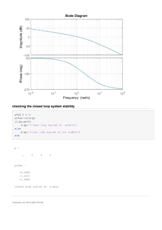
 Construct the bode plot on a semilog Graph-paper for a unity feedback system whose open looptransfer function is given by \(G(S)=\frac{100}{S(S+1)(2+S)} .\) From the bode plot determinea) Gain and phase crossover frequencies.b) Gain and Phase margin, andc) Stability of the closed loop system
1) (10 pts) Consider the unity feedback system shown in the figure: For each of the...
 1) (10 pts) Consider the unity feedback system shown in the figure: For each of the following transfer function G(s), plot its Bode plots using Matlab command "bode", and then work on the plots to find out the crossover frequency phase margin . the phase crossover frequency and the gain margin GM: (a) G(s)= , the S+4 s(s + l)(s + 2)(s +10) (b) Gs)100
A unity gain negative feedback system has an open-loop transfer function given by 4. s) =...
 A unity gain negative feedback system has an open-loop transfer function given by 4. s) = s(1 + 10s)(1 + 10s)? Draw a Bode diagram for this system and determine the loop gain K required for a phase margin of 20 deg. What is the gain margin? 5. We are given the closed-loop transfer function 10(s + 1) T(s) = 82+98+10 for a "unity feedback" system and asked to find the open-loop transfer function, generate a log-magnitude-phase plot for both...
Y(s) C(s) G(s) R(S) Figure 1: Closed-loop system Q2 Consider the setup in Figure 1 with S s1 (i) ...
 Y(s) C(s) G(s) R(S) Figure 1: Closed-loop system Q2 Consider the setup in Figure 1 with S s1 (i) Design a K,τ, α in the lead compensator 1TOS so that the closed-loop system shown in Figure 1 has a steady state error of.0 for a unit ramp reference input at R and a phase margin of about 45 degrees K, α, τ without Bode plots. When you add phase with the lead compensator add an additional 10 degrees of phase....
P4) Consider a system with open loop transfer function of G(s) ? a) Sketch the Bode...
 P4) Consider a system with open loop transfer function of G(s) ? a) Sketch the Bode plot. b) Design a PI controller to make the system have a phase margin of 45°. Assume that the open loop s+1)3 gain results in acceptable steady-state error
 3. Design a PI or PD controller for the system G(8) = s(s+10) to meet the following specifications • Zero steady state error for unit step reference input • tr< 0.12 - . %OS < 10%. (a) Determine the low frequency gain, crossover frequency and phase margin necessary to meet the specifications. (b) Decide if C(s) needs an integrator. Plot the Bode plot of either G(s) or G(s)/s, depending on your choice. (c) Use sisotool (or iteration) to choose a...
 Spring 2019 3. Given a closed-loop control system with unity feedback is shown in the block diagram. G(s) is the open-loop transfer function, and the controller is a gain, K. 1. (20) Calculate the open-loop transfer function tar →Q--t G(s) (10) Calculate the steady-state error to a step input of the open-loop system. 7. (in Bode Form) from the Bode plot. (10) Calculate the shortest possible settling time with a percentage overshoot of 5% or less. 8. 2. (10)Plot the...
 G) r(t) Figure 1: Feedback control system A pulley and belt transmission has a linearized relationship between the driven pulley angle θ(t) in degrees and the input torque u(t) in Newton meters given by the following differential equation du(t) A feedback control system (illustrated in Figure 1) needs to be designed such that the closed-loop system is asymptotically stable and such that the following design criteria are met: 1. the gain crossover frequency a should be between and a 2....
 Answer all parts and show all work.
Design a Pl or PDcontroller for the system Go)+ 10 to meet the following specifications Zero steady state error for unit step reference input ·4 < 0.12s . %OS < 10%. (a) Determine the low frequency gain, crossover frequency and phase margin necessary to meet the (b) Decide if C() needs an integrator. Plot the Bode plot of either G(s) or G(o)/s, depending on (c) Use sisotool (or iteration) to choose a gain...
Answer all parts and show all work.
Design a Pl or PDcontroller for the system Go)+ 10 to meet the following specifications Zero steady state error for unit step reference input ·4 < 0.12s . %OS < 10%. (a) Determine the low frequency gain, crossover frequency and phase margin necessary to meet the (b) Decide if C() needs an integrator. Plot the Bode plot of either G(s) or G(o)/s, depending on (c) Use sisotool (or iteration) to choose a gain...
 Construct the bode plot on a semilog Graph-paper for a unity feedback system whose open looptransfer function is given by \(G(S)=\frac{100}{S(S+1)(2+S)} .\) From the bode plot determinea) Gain and phase crossover frequencies.b) Gain and Phase margin, andc) Stability of the closed loop system
 1) (10 pts) Consider the unity feedback system shown in the figure: For each of the following transfer function G(s), plot its Bode plots using Matlab command "bode", and then work on the plots to find out the crossover frequency phase margin . the phase crossover frequency and the gain margin GM: (a) G(s)= , the S+4 s(s + l)(s + 2)(s +10) (b) Gs)100
 A unity gain negative feedback system has an open-loop transfer function given by 4. s) = s(1 + 10s)(1 + 10s)? Draw a Bode diagram for this system and determine the loop gain K required for a phase margin of 20 deg. What is the gain margin? 5. We are given the closed-loop transfer function 10(s + 1) T(s) = 82+98+10 for a "unity feedback" system and asked to find the open-loop transfer function, generate a log-magnitude-phase plot for both...
 Y(s) C(s) G(s) R(S) Figure 1: Closed-loop system Q2 Consider the setup in Figure 1 with S s1 (i) Design a K,τ, α in the lead compensator 1TOS so that the closed-loop system shown in Figure 1 has a steady state error of.0 for a unit ramp reference input at R and a phase margin of about 45 degrees K, α, τ without Bode plots. When you add phase with the lead compensator add an additional 10 degrees of phase....
 P4) Consider a system with open loop transfer function of G(s) ? a) Sketch the Bode plot. b) Design a PI controller to make the system have a phase margin of 45°. Assume that the open loop s+1)3 gain results in acceptable steady-state error
Most questions answered within 3 hours.
-
PLEASE HELP, NO ONE IS ANSWERING MY QUESTION AND IT IS SUE TODAY
WORTH 20% OF...
asked 5 minutes ago -
α = 0.0007889 T, I = 2.9 A
Other Magnetic Fields: First, based on your
value...
asked 4 minutes ago -
This assignment is a continuation of the 2nd one. You as a HR
Manager, select an...
asked 7 minutes ago -
Hastings Entertainment has a beta of 0.64. If the market return
is expected to be 13.80...
asked 18 minutes ago -
9. Depository institutions are always:
a. illiquid
b. profitable
c. insolvent
d. all of the above...
asked 26 minutes ago -
Use AstroTurf Company's income statement below to answer the
following two questions. Answer these questions with...
asked 26 minutes ago -
How is a firm's task
environment different from its general environment? Provide
examples of both types...
asked 24 minutes ago -
What is one reason Innovators can adopt innovations so
early?
Group of answer choices
they are...
asked 27 minutes ago -
Show that min x^2, s.t. x>=2 has strong duality.
asked 27 minutes ago -
Using curved arrows show how the intermediate formed in this
reaction (Hexaphenylbenzene is prepared through a...
asked 32 minutes ago -
Two lightbulbs operate on the same current. Bulb A has four
times the power output of...
asked 29 minutes ago -
1. What five (5) basic parameters need to be measured
during a pump test in order...
asked 40 minutes ago