
Homework Answers

using given data and relevant equations we can find the required variables
as per guideliens only first four parts are to be solve dfor rest parts post separatley qs again
for any doubts write in comments
Add Answer to:
The system below shows a simplified schematic of an oil transfer system between tanks, from left...
02. centrifugal pump draws benzene at 25°C (sp. weight of benzene 8.59 kN/m) om a tank whose level is 2.6 m below the pump inlet. The atmospheric pressure (abs). The head loss in the suction pipi...
 02. centrifugal pump draws benzene at 25°C (sp. weight of benzene 8.59 kN/m) om a tank whose level is 2.6 m below the pump inlet. The atmospheric pressure (abs). The head loss in the suction piping due to friction and minor osses is 0.8 N.m /N. The vapor pressure of benzene is 13.3 kPa (abs). Determine he available net positive suction head (NPSH) and tell f it is acceptable or not. (10 points) Discharge ine Flew 2.6 m What is...
A fire pumper pumps 150 gpm of water from a fire hydrant through 250 feet of...
A fire pumper pumps 150 gpm of water from a fire hydrant through 250 feet of 2.5" c=120 fire hose. 50 feet of the hose are on the suction side of the pump with the remaining 200 feet are on the discharge side. The hydrant and the pump are at the same elevation and the pressure in the hydrant is 20 psi. The velocity head in the source main is negligible. The discharge is through a 1.5 inch nozzle at...
Water at 15° is flowing at the rate of 14.4m²/hr (Fig. 2). The head added by...
 Water at 15° is flowing at the rate of 14.4m²/hr (Fig. 2). The head added by the pump is equivalent to 80 m. Both tanks are vented. Suction line is 15m long and discharge line is 200m long. Both suction and discharge lines are standard 2-inch (5.1cm) clean steel pipe with roughness value of ε = 5.1 x 10⁸m. Assume that the entrance from Tankl is through a rounded inlet with inlet radius of 10mm and that the elbows are...
4. The discharge pressure gauge reading is 5 lb/in2 (psi) for the pumping system shown in the ske...
 4. The discharge pressure gauge reading is 5 lb/in2 (psi) for the pumping system shown in the sketch below, with the outlet nozzle discharging a 2-inch diameter stream of water directly to the atmosphere. The gauge pressure at the pump suction inlet at the point of incipient cavitation is (-2,071.12) lb/ft, i.e., for vapor pressure of water at 68° F of 50.54 lb/ft2 absolute, and standard atmospheric pressure 30 in Hg. Friction losses in the suction piping from the reservoir...
Problem 2: Figure shows a pump and pipe network being used to transport heptane at 80F...
 Problem 2: Figure shows a pump and pipe network being used to transport heptane at 80F to a large, elevated storage tank that is closed, but vented to ensure that the pressure above the hetane is atmospheric. The volumetric fiow rate of the heptane is 400 gpm. (a) Determine the pressure drop (psi) that the pump must overcome Liquid level Large covered and vented storagt tank Al pipes are 6-nom sid cast iron Al fattings and valves are 6 nom...
Water at 15° is flowing at the rate of 14.4m/hr (Fig. 2). The head added by...
 Water at 15° is flowing at the rate of 14.4m/hr (Fig. 2). The head added by the pump is equivalent to 80 m. Both tanks are vented. Suction line is 15m long and discharge line is 200m long. Both suction and discharge lines are standard 2-inch (5.1cm) clean steel pipe with roughness value of s=5.1 x 10ʻm. Assume that the entrance from Tankl is through a rounded inlet with inlet radius of 10mm and that the elbows are standard 90°....
1- Calculate the net positive suction head (NPSH) of the pump using the following data. i) - Vapo...
 1- Calculate the net positive suction head (NPSH) of the pump using the following data. i) - Vapor pressure of liquid -2.685 x 10⁴ Pa i) - Distance between the level of liquid in the reservoir and suction line 1.2 m. The pump is above the liquid level. ii) -The density of liquid 865 kg/m3 iv)- Friction in the suction line 3.5 J/kg v) - Reservoir is open to atmosphere 2- Liquid octane shall be drawn from an open suction...
As we learned, one must be careful, when placing a pump, to avoid cavitation, the likelihood...
 As we learned, one must be careful, when placing a pump, to avoid cavitation, the likelihood of which is characterized by the Net Positive Suction Head. Using a pump to 'pull' fluid up (rather than push) can lead to cavitation if the available NPSH falls below the required NPSH (required by the pump). Well, using a pump to pull' fluid horizontally can also cause cavitation. Consider the sketch below. The pump is 2 m below the free surface of the...
(b) A schematic diagram of a simple transport system designed to transport oil over a lon distanc...
 (b) A schematic diagram of a simple transport system designed to transport oil over a lon distance. A schematic diagram of the system is illustrated in Figure 3(b). The elevations of free surfaces of tanks 1 and 2 from a common ground level are measured to be 100 m and 145 m respectively. The tanks are connected with 300-m long a circular pipe of diameter 50 cm The supply curve of the pump connected is given in Figure 3(c) Express...
7.14 The pump in Fig. 7.20 delivers water from the lower to the upper reservoir at the rate of 0.057 m3/s. The energy loss between the suction pipe inlet and the pump is 1.83 m and that between t...
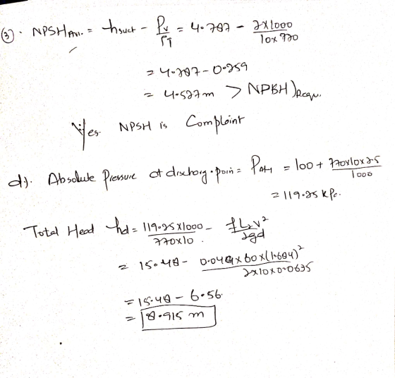
 7.14 The pump in Fig. 7.20 delivers water from the lower to the upper reservoir at the rate of 0.057 m3/s. The energy loss between the suction pipe inlet and the pump is 1.83 m and that between the pump outlet and the upper reservoir is 3.66 m. Both pipes are 6-in Schedule 40 steel pipe. Calculate (a) the pressure at the pump inlet, (b) the pressure at the pump outlet, (c) the total head on the pump, and (d)...
 02. centrifugal pump draws benzene at 25°C (sp. weight of benzene 8.59 kN/m) om a tank whose level is 2.6 m below the pump inlet. The atmospheric pressure (abs). The head loss in the suction piping due to friction and minor osses is 0.8 N.m /N. The vapor pressure of benzene is 13.3 kPa (abs). Determine he available net positive suction head (NPSH) and tell f it is acceptable or not. (10 points) Discharge ine Flew 2.6 m What is...
 Water at 15° is flowing at the rate of 14.4m²/hr (Fig. 2). The head added by the pump is equivalent to 80 m. Both tanks are vented. Suction line is 15m long and discharge line is 200m long. Both suction and discharge lines are standard 2-inch (5.1cm) clean steel pipe with roughness value of ε = 5.1 x 10⁸m. Assume that the entrance from Tankl is through a rounded inlet with inlet radius of 10mm and that the elbows are...
 4. The discharge pressure gauge reading is 5 lb/in2 (psi) for the pumping system shown in the sketch below, with the outlet nozzle discharging a 2-inch diameter stream of water directly to the atmosphere. The gauge pressure at the pump suction inlet at the point of incipient cavitation is (-2,071.12) lb/ft, i.e., for vapor pressure of water at 68° F of 50.54 lb/ft2 absolute, and standard atmospheric pressure 30 in Hg. Friction losses in the suction piping from the reservoir...
 Problem 2: Figure shows a pump and pipe network being used to transport heptane at 80F to a large, elevated storage tank that is closed, but vented to ensure that the pressure above the hetane is atmospheric. The volumetric fiow rate of the heptane is 400 gpm. (a) Determine the pressure drop (psi) that the pump must overcome Liquid level Large covered and vented storagt tank Al pipes are 6-nom sid cast iron Al fattings and valves are 6 nom...
 Water at 15° is flowing at the rate of 14.4m/hr (Fig. 2). The head added by the pump is equivalent to 80 m. Both tanks are vented. Suction line is 15m long and discharge line is 200m long. Both suction and discharge lines are standard 2-inch (5.1cm) clean steel pipe with roughness value of s=5.1 x 10ʻm. Assume that the entrance from Tankl is through a rounded inlet with inlet radius of 10mm and that the elbows are standard 90°....
 1- Calculate the net positive suction head (NPSH) of the pump using the following data. i) - Vapor pressure of liquid -2.685 x 10⁴ Pa i) - Distance between the level of liquid in the reservoir and suction line 1.2 m. The pump is above the liquid level. ii) -The density of liquid 865 kg/m3 iv)- Friction in the suction line 3.5 J/kg v) - Reservoir is open to atmosphere 2- Liquid octane shall be drawn from an open suction...
 As we learned, one must be careful, when placing a pump, to avoid cavitation, the likelihood of which is characterized by the Net Positive Suction Head. Using a pump to 'pull' fluid up (rather than push) can lead to cavitation if the available NPSH falls below the required NPSH (required by the pump). Well, using a pump to pull' fluid horizontally can also cause cavitation. Consider the sketch below. The pump is 2 m below the free surface of the...
 (b) A schematic diagram of a simple transport system designed to transport oil over a lon distance. A schematic diagram of the system is illustrated in Figure 3(b). The elevations of free surfaces of tanks 1 and 2 from a common ground level are measured to be 100 m and 145 m respectively. The tanks are connected with 300-m long a circular pipe of diameter 50 cm The supply curve of the pump connected is given in Figure 3(c) Express...
 7.14 The pump in Fig. 7.20 delivers water from the lower to the upper reservoir at the rate of 0.057 m3/s. The energy loss between the suction pipe inlet and the pump is 1.83 m and that between the pump outlet and the upper reservoir is 3.66 m. Both pipes are 6-in Schedule 40 steel pipe. Calculate (a) the pressure at the pump inlet, (b) the pressure at the pump outlet, (c) the total head on the pump, and (d)...
Most questions answered within 3 hours.
-
Donna is 18 years old and full time accounting student.She is
saving for an overseas holiday...
asked 1 minute from now -
Service-oriented architectures (SOA) provide
object-oriented architectures for web platforms that represent a
collection of services. SOA...
asked 50 seconds from now -
Le Terroir Winery is considering an expansion project to produce
fine wines. The trial expansion will...
asked 8 minutes ago -
The Bahraini public budget experiences deficit in the last
seven years, what are procedures are taken...
asked 15 minutes ago -
You invested $30,000 in a mutual fund at the beginning of the
year when the NAV...
asked 18 minutes ago -
Would you expect the price elasticity of supply for guitars to
be more inelastic in the...
asked 20 minutes ago -
A snowmobile is originally at the point with position vector
30.1 m at 95.0° counterclockwise from...
asked 20 minutes ago -
MAN3240 Organizational Behavior
In one to two paragraphs
6.) How can understanding emotions make me more...
asked 28 minutes ago -
Identify one individual who, in your opinion, is an excellent
leader. List the qualities that this...
asked 26 minutes ago -
For the data set shown below, complete parts (a) through (d)
below. x 3 4 5...
asked 32 minutes ago -
A university administrator working in student housing wants to
determine if the percentage of students residing...
asked 46 minutes ago -
3). Describe human population growth that has occurred in the
past 400 years. Use terms learned...
asked 43 minutes ago