
Homework Answers


Add Answer to:
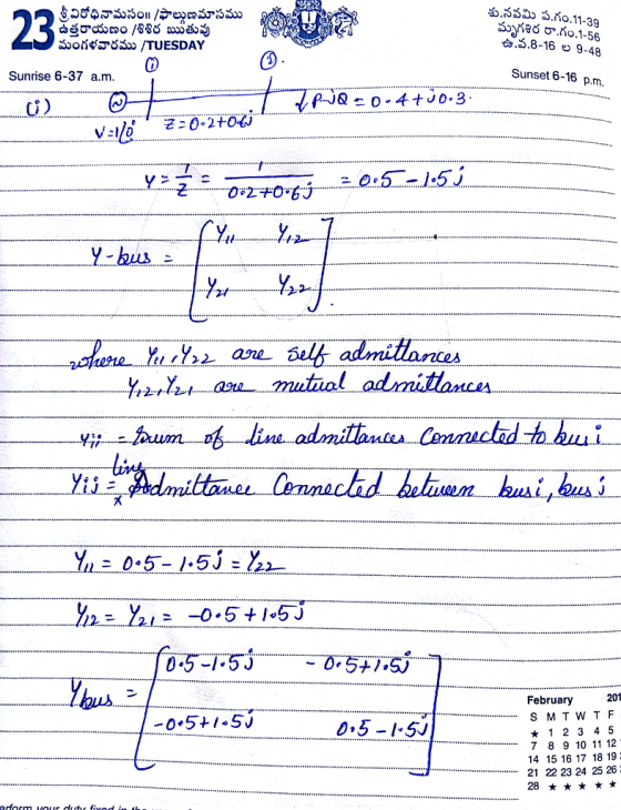
#2. A two bus power system is shown in the figure below. ()Form the bus admittance...
A three-bus system has the bus admittance matrix of Ybus as given below. Calculate the value of V...
 A three-bus system has the bus admittance matrix of Ybus as given below. Calculate the value of V2 and Vj after 2 iterations using the Gauss-Seidel method. Assume Bus 1 as the slack bus with Vi1.00 and Bus 2 and 3 are load buses with S,-1+ј0.5 p.u. and S3-15+j0.75 p.u. Use voltage guesses of 1.020° at both Bus 2 and 3. bus
A three-bus system has the bus admittance matrix of Ybus as given below. Calculate the value of V2...
A three-bus system has the bus admittance matrix of Ybus as given below. Calculate the value of V2 and Vj after 2 iterations using the Gauss-Seidel method. Assume Bus 1 as the slack bus with Vi1.00 and Bus 2 and 3 are load buses with S,-1+ј0.5 p.u. and S3-15+j0.75 p.u. Use voltage guesses of 1.020° at both Bus 2 and 3. bus
A three-bus system has the bus admittance matrix of Ybus as given below. Calculate the value of V2...
1. In the power system network shown in Figure 1, Vi bus 1 is a slack bus with 1.00 per unit and bus 2 is a load bus wi...
 1. In the power system network shown in Figure 1, Vi bus 1 is a slack bus with 1.00 per unit and bus 2 is a load bus with S2 Mvar. The line impedance on a base of 100 MVA is Z = 0.02 + j0.04 per unit (a) Using Gauss-Seidel method, determine V2 . Use an initial estimate of V=1.0j0.0 and perform four iterations (b) If after several iterations voltage at bus 2 converges to V2 = 0.90-j0.10, determine...
Consider the single line diagram of a 3-bus power system shown in Figure 2. Slack bus...
 Consider the single line diagram of a 3-bus power system shown in Figure 2. Slack bus 3 Figure 2. The data for this system are given in Tables 1 and 2. Bus Table 1 Generation Load Assumed PG QGPLQL bus voltage (MW) (MVar) (MW) (MVar) 1.05 +10.0 - - 1.0 + 0.0 50 30 305.6 140.2 1.0 +0.0 0.0 0.0 138.6 45.2 slack bus) Table 2 Bus-to-bus Impedance 0.2 + j0.04 .01 +0.03 2.3 0.0125 + j0.025 (0) Convert all...
The single line diagram of a power network is shown in the figure. Bus#1 is a slack bus. The sche...
 The single line diagram of a power network is shown in the figure. Bus#1 is a slack bus. The scheduled powers for bus#2 and bus#3 are given. The impedances shown in the figure are all in per-unit considering a power base of 100 MVA. 30 400 MW 320 MVAr Slack V-1400.0125 jo.os 3 300 MW 270 MVAr A. Use the Gauss Seidel technique to determine voltages at bus#2 & bus#3. (Start with an initial guess 140 for both buses). [Only...
The single line diagram of a power network is shown in the figure. Bus#1 is a slack bus. The sche...
 Answer part D
The single line diagram of a power network is shown in the figure. Bus#1 is a slack bus. The scheduled powers for bus#2 and bus#3 are given. The impedances shown in the figure are all in per-unit considering a power base of 100 MVA. 30 400 MW 320 MVAr Slack V-140 j0.0125 jo.0s 00 MW 270 MVAr A. Use the Gauss Seidel technique to determine voltages at bus#2 & bus#3. (Start with an initial guess 140 for...
Answer part D
The single line diagram of a power network is shown in the figure. Bus#1 is a slack bus. The scheduled powers for bus#2 and bus#3 are given. The impedances shown in the figure are all in per-unit considering a power base of 100 MVA. 30 400 MW 320 MVAr Slack V-140 j0.0125 jo.0s 00 MW 270 MVAr A. Use the Gauss Seidel technique to determine voltages at bus#2 & bus#3. (Start with an initial guess 140 for...
Question 1: A single line diagram of a three-bus power system is shown in Fig 1....
 Question 1: A single line diagram of a three-bus power system is shown in Fig 1. Bus 1 is the slack bus with a voltage of 1.020 per unit, bus 2 is a voltage-controlled bus (PV-bus) with a voltage magnitude of 1.05 pu and real generated power of 1 00 MWand the reactive power in the range Q.(20MVAR) < Q<Q-60M¥AR .BUS 3 is PQ bus with P 300 MW and Q= 200 Mvar. Take 100 MVÅ susceptance are neglected as...
Q2. i) The one-line diagram of simple three-bus power system with generation at bus 1 is shown in figure Q2. 0.02 + 30.04 2 256.6 MW 0.0125 + 30.025 +110.2 Mvar 0.01 + 30.03 Slack Bus 3 Vi = 1.0520° 138.6 MW 45.2 Mvar Figure Q2 The magnitude of voltage at
Q2. i) The one-line diagram of simple three-bus power system with generation at bus 1 is shown in figure Q2. 0.02 + 30.04 2 256.6 MW 0.0125 + 30.025 +110.2 Mvar 0.01 + 30.03 Slack Bus 3 Vi = 1.0520° 138.6 MW 45.2 Mvar Figure Q2 The magnitude of voltage at bus 1 is adjusted to 1.05 per unit. The scheduled loads at buses 2 and 3 are as marked on the diagram. Line impedances are marked in per unit...
The six-bus system shown in Figure 1 will be simulated using MATLAB. Transmission line data and b...
 The six-bus system shown in Figure 1 will be simulated using MATLAB. Transmission line data and bus data are given in Tables 1 and 2 respectively. The transmission line data are calculated on 100 MVA base and 230 (line-to-line) kV base for generator. Tasks: 1. Determine the network admittance matrix Y 2. Find the load flow solution using Gauss-Seidel/Newton Raphson method until first iteration by manual calculation. Use Maltab software to solve power flow problem using Gauss-Seidel method. Find the...
TI System layout for Problem #1 1. Using the system layout above with Ybus as given...
 TI System layout for Problem #1 1. Using the system layout above with Ybus as given below: a. Develop One iteration of the bus voltages using the Gauss-Seidel method b. Using results in "a" above, find the current and power flows in line L12 Ybus0-60i 0 +20i 0+40i 0-60i 0 +40i 0-80i 0+40i 0 +40i 0 +20i Generator 1 is a slack with Vi 1.025 Generator 2 has power P 3 pu and voltage V2 magnitude -1.03 Bus 3 is...
6.28 Consider the simplified electric power system shown in Figure 6.17 for which the power- flow...
 6.28 Consider the simplified electric power system shown in Figure 6.17 for which the power- flow solution can be obtained without resorting to iterative techniques. (a) Compute the elements of the bus admittance matrix Ybus. (b) Calculate the phase angle δ, by using the real power equation at bus 2 (voltage-controlled bus). (c) Determine IV and os by using both the real and reactive power equations at bus 3 (load bus). (d) Find the real power generated at bus 1...
 A three-bus system has the bus admittance matrix of Ybus as given below. Calculate the value of V2 and Vj after 2 iterations using the Gauss-Seidel method. Assume Bus 1 as the slack bus with Vi1.00 and Bus 2 and 3 are load buses with S,-1+ј0.5 p.u. and S3-15+j0.75 p.u. Use voltage guesses of 1.020° at both Bus 2 and 3. bus
A three-bus system has the bus admittance matrix of Ybus as given below. Calculate the value of V2...
A three-bus system has the bus admittance matrix of Ybus as given below. Calculate the value of V2 and Vj after 2 iterations using the Gauss-Seidel method. Assume Bus 1 as the slack bus with Vi1.00 and Bus 2 and 3 are load buses with S,-1+ј0.5 p.u. and S3-15+j0.75 p.u. Use voltage guesses of 1.020° at both Bus 2 and 3. bus
A three-bus system has the bus admittance matrix of Ybus as given below. Calculate the value of V2...
 1. In the power system network shown in Figure 1, Vi bus 1 is a slack bus with 1.00 per unit and bus 2 is a load bus with S2 Mvar. The line impedance on a base of 100 MVA is Z = 0.02 + j0.04 per unit (a) Using Gauss-Seidel method, determine V2 . Use an initial estimate of V=1.0j0.0 and perform four iterations (b) If after several iterations voltage at bus 2 converges to V2 = 0.90-j0.10, determine...
 Consider the single line diagram of a 3-bus power system shown in Figure 2. Slack bus 3 Figure 2. The data for this system are given in Tables 1 and 2. Bus Table 1 Generation Load Assumed PG QGPLQL bus voltage (MW) (MVar) (MW) (MVar) 1.05 +10.0 - - 1.0 + 0.0 50 30 305.6 140.2 1.0 +0.0 0.0 0.0 138.6 45.2 slack bus) Table 2 Bus-to-bus Impedance 0.2 + j0.04 .01 +0.03 2.3 0.0125 + j0.025 (0) Convert all...
 The single line diagram of a power network is shown in the figure. Bus#1 is a slack bus. The scheduled powers for bus#2 and bus#3 are given. The impedances shown in the figure are all in per-unit considering a power base of 100 MVA. 30 400 MW 320 MVAr Slack V-1400.0125 jo.os 3 300 MW 270 MVAr A. Use the Gauss Seidel technique to determine voltages at bus#2 & bus#3. (Start with an initial guess 140 for both buses). [Only...
 Answer part D
The single line diagram of a power network is shown in the figure. Bus#1 is a slack bus. The scheduled powers for bus#2 and bus#3 are given. The impedances shown in the figure are all in per-unit considering a power base of 100 MVA. 30 400 MW 320 MVAr Slack V-140 j0.0125 jo.0s 00 MW 270 MVAr A. Use the Gauss Seidel technique to determine voltages at bus#2 & bus#3. (Start with an initial guess 140 for...
Answer part D
The single line diagram of a power network is shown in the figure. Bus#1 is a slack bus. The scheduled powers for bus#2 and bus#3 are given. The impedances shown in the figure are all in per-unit considering a power base of 100 MVA. 30 400 MW 320 MVAr Slack V-140 j0.0125 jo.0s 00 MW 270 MVAr A. Use the Gauss Seidel technique to determine voltages at bus#2 & bus#3. (Start with an initial guess 140 for...
 Question 1: A single line diagram of a three-bus power system is shown in Fig 1. Bus 1 is the slack bus with a voltage of 1.020 per unit, bus 2 is a voltage-controlled bus (PV-bus) with a voltage magnitude of 1.05 pu and real generated power of 1 00 MWand the reactive power in the range Q.(20MVAR) < Q<Q-60M¥AR .BUS 3 is PQ bus with P 300 MW and Q= 200 Mvar. Take 100 MVÅ susceptance are neglected as...
 The six-bus system shown in Figure 1 will be simulated using MATLAB. Transmission line data and bus data are given in Tables 1 and 2 respectively. The transmission line data are calculated on 100 MVA base and 230 (line-to-line) kV base for generator. Tasks: 1. Determine the network admittance matrix Y 2. Find the load flow solution using Gauss-Seidel/Newton Raphson method until first iteration by manual calculation. Use Maltab software to solve power flow problem using Gauss-Seidel method. Find the...
 TI System layout for Problem #1 1. Using the system layout above with Ybus as given below: a. Develop One iteration of the bus voltages using the Gauss-Seidel method b. Using results in "a" above, find the current and power flows in line L12 Ybus0-60i 0 +20i 0+40i 0-60i 0 +40i 0-80i 0+40i 0 +40i 0 +20i Generator 1 is a slack with Vi 1.025 Generator 2 has power P 3 pu and voltage V2 magnitude -1.03 Bus 3 is...
 6.28 Consider the simplified electric power system shown in Figure 6.17 for which the power- flow solution can be obtained without resorting to iterative techniques. (a) Compute the elements of the bus admittance matrix Ybus. (b) Calculate the phase angle δ, by using the real power equation at bus 2 (voltage-controlled bus). (c) Determine IV and os by using both the real and reactive power equations at bus 3 (load bus). (d) Find the real power generated at bus 1...
Most questions answered within 3 hours.
-
A point charge with charge q1 = 4.00 μC is held stationary at
the origin. A...
asked 10 seconds from now -
describe conditions and outcomes of boiling
pasteurization and surfacing. which of these treatment can be
considered...
asked 1 minute ago -
In a poll of 504 human resource professionals, 46.4% said that
body piercings and tattoos were...
asked 1 minute ago -
AdrenalineAdrenaline
Sports Company makes snowboards, downhill skis, cross-country
skis, skateboards, surfboards, and in-line skates. The company...
asked 4 minutes ago -
Compare the Forfaiting and Factoring forms of export
financing
asked 7 minutes ago -
Europe in the 19th century was not dominated by:
a. the scientific quest
b. economic collectivism...
asked 16 minutes ago -
"The economic theory suggests that consumers will not shop at or
spend their money with a...
asked 20 minutes ago -
In your opinion, which provides the most benefit to an
organization, a budget or the budgeting...
asked 30 minutes ago -
What features are centralized in your web application by master
pages? How are master pages implemented...
asked 27 minutes ago -
Write the expression for the molecular wavefunction of (i) a
s-pz sigma bond and (ii) a...
asked 35 minutes ago -
It costs Crane Company $28 of variable costs and $10.00 of
allocated fixed costs to produce...
asked 49 minutes ago -
Explain the following basis of electron configuration i) the
electron affinity of S is +200kJ mol-1
asked 58 minutes ago