
Homework Answers
Add Answer to:
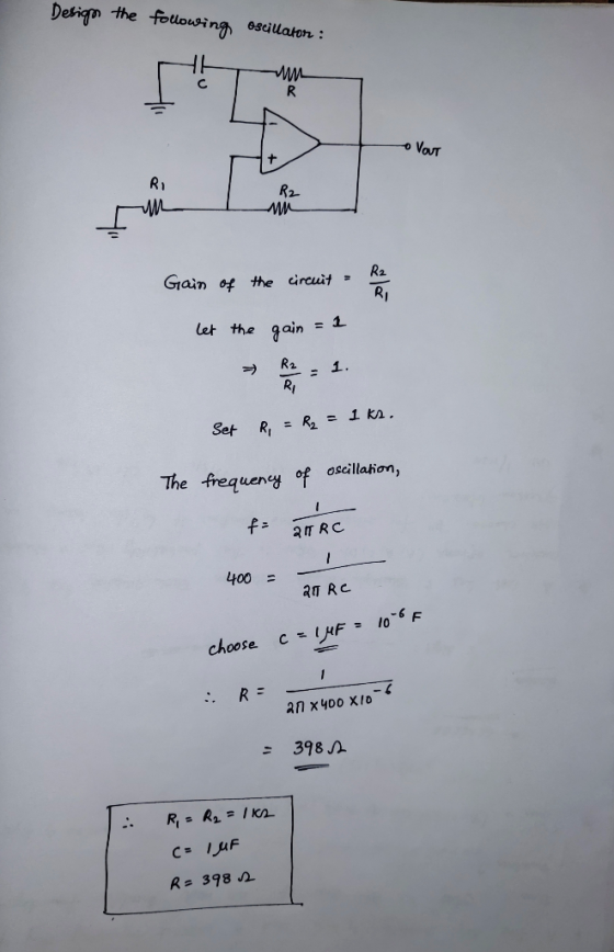
Circuit 8 Using a single op amp, design an oscillator which produces a 400 hz output...
1- Design a lossy integrator op-amp circuit using op-amp 741. First, derive an expression for - V...
 UPLOAD PSPICE SIMULATION TO VERIFY CALCULATIONS
1- Design a lossy integrator op-amp circuit using op-amp 741. First, derive an expression for - Vo Then assign values to circuit components in order to have Gai 1. Verify your design with a PSpice simulation. Since gain value depends on Vi frequency, perform an AC sweep analysis (frequency response) to obtain which frequency gives you this gain. Report this trequency. IVil
1- Design a lossy integrator op-amp circuit using op-amp 741. First, derive...
UPLOAD PSPICE SIMULATION TO VERIFY CALCULATIONS
1- Design a lossy integrator op-amp circuit using op-amp 741. First, derive an expression for - Vo Then assign values to circuit components in order to have Gai 1. Verify your design with a PSpice simulation. Since gain value depends on Vi frequency, perform an AC sweep analysis (frequency response) to obtain which frequency gives you this gain. Report this trequency. IVil
1- Design a lossy integrator op-amp circuit using op-amp 741. First, derive...
Op Amp Integrators and Differentiators 1.) Design an op-amp circuit that acts as an integrator. Chose...
 Op Amp Integrators and Differentiators 1.) Design an op-amp circuit that acts as an integrator. Chose R and C values to give you a gain of 5 at f-1kHz Draw out the circuit and show the input and output, label all the pin numbers and show where the +-12 power supply connections for the chip are. Turn in the circuit diagram, carefully labelled 2.) Build your circuit and measure the gain as a function of frequency. Collect enough data to...
ONLY NEED HELP WITH C AND D PLEASE! The differentiator circuit shown in Figure 1 uses an op-amp with ideal characteristics C1 Figure 1 (a) Prove that the gain of the circuit is given by the following...
 ONLY NEED HELP WITH C AND D PLEASE!
The differentiator circuit shown in Figure 1 uses an op-amp with ideal characteristics C1 Figure 1 (a) Prove that the gain of the circuit is given by the following expression using first principles for an ideal op-amp (2 marks) Gain = - (1 + juli R 1) (b) If the differentiator frequency (at unity gain) is 100Hz and the high frequency gain is 40dB and R2 is 220kQ, design the rest of...
ONLY NEED HELP WITH C AND D PLEASE!
The differentiator circuit shown in Figure 1 uses an op-amp with ideal characteristics C1 Figure 1 (a) Prove that the gain of the circuit is given by the following expression using first principles for an ideal op-amp (2 marks) Gain = - (1 + juli R 1) (b) If the differentiator frequency (at unity gain) is 100Hz and the high frequency gain is 40dB and R2 is 220kQ, design the rest of...
Design and set up a circuit using basic op-amp configuration that will implement a mathematical expression...
Design and set up a circuit using basic op-amp configuration that will implement a mathematical expression Y = 3A-2B-C (where A, B, and C are the inputs and Y is the out of the circuit). Then verify the design for A = 3V, B = 1V, and C = -2V. (Hint: Generate these input voltages from a 5V DC source). Use resistor values of the order of 100K ohms for the feedback and input resistors in the op-amp circuit. Note:...
1. Use supply voltage +/- 15V and design a comparator op-amp circuit where the output becomes...
1. Use supply voltage +/- 15V and design a comparator op-amp circuit where the output becomes maximum positive when the input is higher then 5V. 2. Sketch the output voltage relative to the input voltage of the circuit. 3. How can we get maximum negative output voltage when the input voltage is bigger then 5V?
Design an amplifier that produces the following output equation. You may use only one op-amp and...
 Design an amplifier that produces the following output equation.
You may use only one op-amp and resistors with values:
1k<R<100k.
For the following minimum phase systems, given the Magnitude
plots indicate if the phase plot is correct. Explain.
Questions from Chapter 1, Sections 1.4 (10 points): 2.1 Design an amplifier that produces the following output equation. You may use only one op-amp and resistors with values: 1k <R <100k Rt 2 Vo Ry レ
Design an amplifier that produces the following output equation.
You may use only one op-amp and resistors with values:
1k<R<100k.
For the following minimum phase systems, given the Magnitude
plots indicate if the phase plot is correct. Explain.
Questions from Chapter 1, Sections 1.4 (10 points): 2.1 Design an amplifier that produces the following output equation. You may use only one op-amp and resistors with values: 1k <R <100k Rt 2 Vo Ry レ
Op-Amp Circuit Stability Although op-amps behave as single-pole amplifiers which are "uncondition...
 Op-Amp Circuit Stability Although op-amps behave as single-pole amplifiers which are "unconditionally stable," it's still possible to make unstable amplifiers if you don't know what you're doing. The most famous example of this is the voltage differentiator 1. Consider the following circuit: a. Find the expression for this amplifier's ideal gain Aco (s), assuming the op-amp is ideal (a(s) - o. Hint: It's just an inverting amplifier with z and z2 R (5pts) b. Suppose the gain-setting components have values...
need help with C and D please The differentiator circuit shown in Figure 1 uses an op-amp with ideal characteristics. R2 R1 C1 Vi O Figure 1 (c) Sketch the Bode magnitude response for this circ...
 need help with C and D please
The differentiator circuit shown in Figure 1 uses an op-amp with ideal characteristics. R2 R1 C1 Vi O Figure 1 (c) Sketch the Bode magnitude response for this circuit for the frequency range of 10° to 108 Hz. (7 marks) (d) Sketch the output waveform of the differentiator and justify your answer, if v is as shown in Figure 2 with a period of: () 100 ms (ii) 10 us (6 marks) 0.11...
need help with C and D please
The differentiator circuit shown in Figure 1 uses an op-amp with ideal characteristics. R2 R1 C1 Vi O Figure 1 (c) Sketch the Bode magnitude response for this circuit for the frequency range of 10° to 108 Hz. (7 marks) (d) Sketch the output waveform of the differentiator and justify your answer, if v is as shown in Figure 2 with a period of: () 100 ms (ii) 10 us (6 marks) 0.11...
4. Using resistor values in the 1 kOto 100 ㏀ range, design an op amp circuit...
 4. Using resistor values in the 1 kOto 100 ㏀ range, design an op amp circuit that has the following output voltage vout, where va, Vb, Ve and va are input voltages. Use as many op amps as you like
Chapter 4, Problem 4.48 Design an op-amp circuit that has the following input/output relationship Vo 21V1+...
 Chapter 4, Problem 4.48 Design an op-amp circuit that has the following input/output relationship Vo 21V1+ 0.5V2 Use the circuit shown below: V20 RA R2 Vi If RB-1 k? and R 1-1 ks, find (a) RA and (b) R2. Click if you would like to Show Work for this question: Open Show Work
 UPLOAD PSPICE SIMULATION TO VERIFY CALCULATIONS
1- Design a lossy integrator op-amp circuit using op-amp 741. First, derive an expression for - Vo Then assign values to circuit components in order to have Gai 1. Verify your design with a PSpice simulation. Since gain value depends on Vi frequency, perform an AC sweep analysis (frequency response) to obtain which frequency gives you this gain. Report this trequency. IVil
1- Design a lossy integrator op-amp circuit using op-amp 741. First, derive...
UPLOAD PSPICE SIMULATION TO VERIFY CALCULATIONS
1- Design a lossy integrator op-amp circuit using op-amp 741. First, derive an expression for - Vo Then assign values to circuit components in order to have Gai 1. Verify your design with a PSpice simulation. Since gain value depends on Vi frequency, perform an AC sweep analysis (frequency response) to obtain which frequency gives you this gain. Report this trequency. IVil
1- Design a lossy integrator op-amp circuit using op-amp 741. First, derive...
 Op Amp Integrators and Differentiators 1.) Design an op-amp circuit that acts as an integrator. Chose R and C values to give you a gain of 5 at f-1kHz Draw out the circuit and show the input and output, label all the pin numbers and show where the +-12 power supply connections for the chip are. Turn in the circuit diagram, carefully labelled 2.) Build your circuit and measure the gain as a function of frequency. Collect enough data to...
 ONLY NEED HELP WITH C AND D PLEASE!
The differentiator circuit shown in Figure 1 uses an op-amp with ideal characteristics C1 Figure 1 (a) Prove that the gain of the circuit is given by the following expression using first principles for an ideal op-amp (2 marks) Gain = - (1 + juli R 1) (b) If the differentiator frequency (at unity gain) is 100Hz and the high frequency gain is 40dB and R2 is 220kQ, design the rest of...
ONLY NEED HELP WITH C AND D PLEASE!
The differentiator circuit shown in Figure 1 uses an op-amp with ideal characteristics C1 Figure 1 (a) Prove that the gain of the circuit is given by the following expression using first principles for an ideal op-amp (2 marks) Gain = - (1 + juli R 1) (b) If the differentiator frequency (at unity gain) is 100Hz and the high frequency gain is 40dB and R2 is 220kQ, design the rest of...
 Design an amplifier that produces the following output equation.
You may use only one op-amp and resistors with values:
1k<R<100k.
For the following minimum phase systems, given the Magnitude
plots indicate if the phase plot is correct. Explain.
Questions from Chapter 1, Sections 1.4 (10 points): 2.1 Design an amplifier that produces the following output equation. You may use only one op-amp and resistors with values: 1k <R <100k Rt 2 Vo Ry レ
Design an amplifier that produces the following output equation.
You may use only one op-amp and resistors with values:
1k<R<100k.
For the following minimum phase systems, given the Magnitude
plots indicate if the phase plot is correct. Explain.
Questions from Chapter 1, Sections 1.4 (10 points): 2.1 Design an amplifier that produces the following output equation. You may use only one op-amp and resistors with values: 1k <R <100k Rt 2 Vo Ry レ
 Op-Amp Circuit Stability Although op-amps behave as single-pole amplifiers which are "unconditionally stable," it's still possible to make unstable amplifiers if you don't know what you're doing. The most famous example of this is the voltage differentiator 1. Consider the following circuit: a. Find the expression for this amplifier's ideal gain Aco (s), assuming the op-amp is ideal (a(s) - o. Hint: It's just an inverting amplifier with z and z2 R (5pts) b. Suppose the gain-setting components have values...
 need help with C and D please
The differentiator circuit shown in Figure 1 uses an op-amp with ideal characteristics. R2 R1 C1 Vi O Figure 1 (c) Sketch the Bode magnitude response for this circuit for the frequency range of 10° to 108 Hz. (7 marks) (d) Sketch the output waveform of the differentiator and justify your answer, if v is as shown in Figure 2 with a period of: () 100 ms (ii) 10 us (6 marks) 0.11...
need help with C and D please
The differentiator circuit shown in Figure 1 uses an op-amp with ideal characteristics. R2 R1 C1 Vi O Figure 1 (c) Sketch the Bode magnitude response for this circuit for the frequency range of 10° to 108 Hz. (7 marks) (d) Sketch the output waveform of the differentiator and justify your answer, if v is as shown in Figure 2 with a period of: () 100 ms (ii) 10 us (6 marks) 0.11...
 4. Using resistor values in the 1 kOto 100 ㏀ range, design an op amp circuit that has the following output voltage vout, where va, Vb, Ve and va are input voltages. Use as many op amps as you like
 Chapter 4, Problem 4.48 Design an op-amp circuit that has the following input/output relationship Vo 21V1+ 0.5V2 Use the circuit shown below: V20 RA R2 Vi If RB-1 k? and R 1-1 ks, find (a) RA and (b) R2. Click if you would like to Show Work for this question: Open Show Work
Most questions answered within 3 hours.
-
Four forces act on an object, given by A = 41.3 N east, B = 46.3...
asked 28 minutes ago -
Which of the following design considerations leads to more
user-friendly presentation layers for GUIs? [Check all...
asked 1 hour ago -
38%
of adults say cashews are their favorite kind of nut. You
randomly select 12 adults...
asked 3 hours ago -
Notational Inc. is considering installing a new server. The
machine costs $100,000 and is expected to...
asked 3 hours ago -
Given the information coding of DNA strand:
5'-TTT-TAC-GAA-GAG-TGA-3',
Write the corresponding DNA template and mRNA strand...
asked 3 hours ago -
2. Boris recently synthesized an explosive compound he named
Badenoughium. The molecular formula for Bdenoughium is...
asked 7 hours ago -
5. A car decelerate evenly from a velocity of 50mph until rest
in a distance of...
asked 7 hours ago -
IN HTML Programming
1. Write a script that inputs integers (one at a time) and
passes...
asked 7 hours ago -
A dentist uses a mirror to examine a tooth that is 0.75 cm in
front of...
asked 7 hours ago -
You set up a 100,000 line of credit for the business on 1/1/X8,
annual interest is...
asked 7 hours ago -
What is the measurement uncertainty of a pan balance? How did you
get that?
asked 7 hours ago -
Suppose four firms have market shares of 30%, 30%, 20% and 20%.
What is the Herfindahl-Hirschman...
asked 7 hours ago