
need help with C and D please

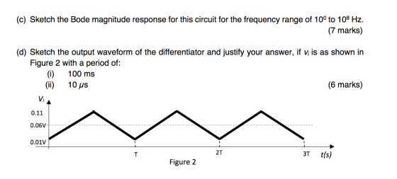
(c) Sketch the Bode magnitude response for this circuit for the frequency range of 10° to 108 Hz. (7 marks) (d) Sketch the output waveform of the differentiator and justify your answer, if v is as shown in Figure 2 with a period of: () 100 ms (ii) 10 us (6 marks) 0.11 0.06V 0.01v T t(s) 2T Figure 2
Problem The differentiator circuit shown in Figure 1 uses an op-amp with ideal characteristics. R2 R, C1 Vi Figure 1 (a) Prove that the gain of the circuit is given by the following expression using first principles for (2 marks) an ideal op-amp: Gain V1 +jCR1) (b) If the differentiator frequency (at unity gain) is 100Hz and the high frequency gain is 40dB, (6 marks) and R2 is 220kQ, design the rest of the component values Page 1 of 3
Homework Answers


Add Answer to:
need help with C and D please The differentiator circuit shown in Figure 1 uses an op-amp with ideal characteristics. R2 R1 C1 Vi O Figure 1 (c) Sketch the Bode magnitude response for this circ...
ONLY NEED HELP WITH C AND D PLEASE! The differentiator circuit shown in Figure 1 uses an op-amp with ideal characteristics C1 Figure 1 (a) Prove that the gain of the circuit is given by the following...
 ONLY NEED HELP WITH C AND D PLEASE!
The differentiator circuit shown in Figure 1 uses an op-amp with ideal characteristics C1 Figure 1 (a) Prove that the gain of the circuit is given by the following expression using first principles for an ideal op-amp (2 marks) Gain = - (1 + juli R 1) (b) If the differentiator frequency (at unity gain) is 100Hz and the high frequency gain is 40dB and R2 is 220kQ, design the rest of...
ONLY NEED HELP WITH C AND D PLEASE!
The differentiator circuit shown in Figure 1 uses an op-amp with ideal characteristics C1 Figure 1 (a) Prove that the gain of the circuit is given by the following expression using first principles for an ideal op-amp (2 marks) Gain = - (1 + juli R 1) (b) If the differentiator frequency (at unity gain) is 100Hz and the high frequency gain is 40dB and R2 is 220kQ, design the rest of...
4. In the in the compensator op-amp circuit below, R1 - IMm, R2- 10 Mn, c1-...
 4. In the in the compensator op-amp circuit below, R1 - IMm, R2- 10 Mn, c1- Find the transfer function H(s)- Vo(s/Vi(s) (i) Find the poles and zeros. (ii) (a) (b) Sketch the poles and zeros in the complex s-plane (c) With s - jo what is the amplitude (magnitude) and phase angle? (d) From part (c) find the amplitude and phase frequencies and fill shown in the table below Comment on the results of (d) (e) | Frequency ω...
ONLY NEED HELP WITH III and IV PLEASE (e) A second stage, shown in Figure 3, is cascaded directly after the output of the circuit in Figure 1 R4 Figure 3 (i) Show that the combined response of the c...
 ONLY NEED HELP WITH III and IV PLEASE
(e) A second stage, shown in Figure 3, is cascaded directly after the output of the circuit in Figure 1 R4 Figure 3 (i) Show that the combined response of the complete circuit is given by: (4 marks) (ii) The two cascaded stages form a bandpass filter, which only amplifies a specific range of frequencies. This range of frequencies is known as the passband. Using the values chosen in (a) for Figure...
ONLY NEED HELP WITH III and IV PLEASE
(e) A second stage, shown in Figure 3, is cascaded directly after the output of the circuit in Figure 1 R4 Figure 3 (i) Show that the combined response of the complete circuit is given by: (4 marks) (ii) The two cascaded stages form a bandpass filter, which only amplifies a specific range of frequencies. This range of frequencies is known as the passband. Using the values chosen in (a) for Figure...
1. Find the operating point of the circuit below assuming the op amp is ideal 2. Estimate the midband voltage gain Avs-...
 1. Find the operating point of the circuit below assuming the op amp is ideal 2. Estimate the midband voltage gain Avs-vo v, 3. Choose values for C1 and C2 so that the pole frequency associated with Ci is 1 Hz and the pole frequency associated with C is 400 Hz. 4. At what frequency fz does a zero occur? 6. Why does the amplifier's gain drop at high frequencies? C2 R1 R2 99K C2] 2K param C2 0.1uF U1...
Assuming an ideal op-amp (1)find the 3dB frequency of the circuit, if R1=1.5 KΩ, R2=13.2 KΩ,...
 Assuming an ideal op-amp (1)find
the 3dB frequency of the circuit, if R1=1.5 KΩ, R2=13.2
KΩ, R3=20 KΩ, and C=5 nF
2)Consider the above circuit with the component
values: R1=13.2 KΩ, R2= 795.77 Ω, R3=20
KΩ, and C=100 nF. Find the angle of the transfer
function in degrees at 2KHz .
- C R2 R1 + Vi(jw) Vo R3 H HI-
Assuming an ideal op-amp (1)find
the 3dB frequency of the circuit, if R1=1.5 KΩ, R2=13.2
KΩ, R3=20 KΩ, and C=5 nF
2)Consider the above circuit with the component
values: R1=13.2 KΩ, R2= 795.77 Ω, R3=20
KΩ, and C=100 nF. Find the angle of the transfer
function in degrees at 2KHz .
- C R2 R1 + Vi(jw) Vo R3 H HI-
A. (10 pts) Implement the voltage amplifier shown below using an ideal op amp circuit. You have o...
 a. (10 pts) Implement the voltage amplifier shown below using an ideal op amp circuit. You have one op amp available for this circuit, and a range of resistors with values from 1 kΩ to 100 ka. Draw the schematic of your op amp circuit, labeling resistor values. Make sure the gain, input resistance, and output resistance of your circuit matches the model in the schematic. R=012 *100v, RL 100 b. (5 pts) Your amplifier circuit should have a frequency...
Derive the transfer function of the circuit in Fig.P2.93(foranidealopamp)andshowthatitcanbewritten in the form Vo Vi = −R2/R1...
 Derive the transfer function of the circuit in
Fig.P2.93(foranidealopamp)andshowthatitcanbewritten in the
form
Vo Vi = −R2/R1 [1+(ω1/jω)][1+j(ω/ω2)] whereω1=1/C1R1
andω2=1/C2R2.Assumingthatthecircuit is designed such that ω2 ω1,
find approximate expressions
for the transfer function in the following frequency regions: (a)
ωω1 (b) ω1 ωω2 (c) ωω2
Vo
FigureP2.93
Use these approximations to sketch a Bode plot for the magnitude
response. Observe that the circuit performs as an amplifier whose
gain rolls off at the low-frequency end in the manner of a
high-pass...
Derive the transfer function of the circuit in
Fig.P2.93(foranidealopamp)andshowthatitcanbewritten in the
form
Vo Vi = −R2/R1 [1+(ω1/jω)][1+j(ω/ω2)] whereω1=1/C1R1
andω2=1/C2R2.Assumingthatthecircuit is designed such that ω2 ω1,
find approximate expressions
for the transfer function in the following frequency regions: (a)
ωω1 (b) ω1 ωω2 (c) ωω2
Vo
FigureP2.93
Use these approximations to sketch a Bode plot for the magnitude
response. Observe that the circuit performs as an amplifier whose
gain rolls off at the low-frequency end in the manner of a
high-pass...
Consider the oscillator circuit shown below. The op amp i s ideal Rb Vo R2 = 10 kΩ L2 100 mH R1 1...
 Consider the oscillator circuit shown below. The op amp i s ideal Rb Vo R2 = 10 kΩ L2 100 mH R1 1 k2 L1 = 10 mH a. What is the frequency of oscillation in Hz? b. Specify the required value of Rb sustain oscillations. c. A limiter circuit is added to oscillator by separating Rb into two series resistors Rb1 and Rb2 as shown in the next page along with two anti-parallel diodes in shunt with Rb2. determine...
need help for d,e,f OP-Amp Circuit R-20k Fig 1 1. Design an operational amplifier circuit using an LM741 op-amp an...
 need help for d,e,f
OP-Amp Circuit R-20k Fig 1 1. Design an operational amplifier circuit using an LM741 op-amp and a 10k the diagram shown in Fig 1 to produce the output voltage feedback resistor that represents Clearly write your ID number in Table 1 Table 1 Your ID Number 3775。73 . Set up the roquired gain numbers as follows and write them in Table 2 Ai- the last digit of your ID number+5 A2-the 2ed last digit of your...
need help for d,e,f
OP-Amp Circuit R-20k Fig 1 1. Design an operational amplifier circuit using an LM741 op-amp and a 10k the diagram shown in Fig 1 to produce the output voltage feedback resistor that represents Clearly write your ID number in Table 1 Table 1 Your ID Number 3775。73 . Set up the roquired gain numbers as follows and write them in Table 2 Ai- the last digit of your ID number+5 A2-the 2ed last digit of your...
Laboratory 1: operation amplifier characteristics A. Objectives: 1. To study the basic characteri...
 thanks
Laboratory 1: operation amplifier characteristics A. Objectives: 1. To study the basic characteristics of an operational amplifier 2. To study the bias circuit of an operational amplifier B. Apparatus: 1. DC Power supply 2. Experimental board and corresponding components 3. Electronic calculator (prepared by students) 4. Digital camera (prepared by students for photo taking of the experimental results) 5. Laptop computer with the software PicoScope 6 and Microsoft Word installed. 6. PicoScope PC Oscilloscope and its accessories. 7. Multimeter...
thanks
Laboratory 1: operation amplifier characteristics A. Objectives: 1. To study the basic characteristics of an operational amplifier 2. To study the bias circuit of an operational amplifier B. Apparatus: 1. DC Power supply 2. Experimental board and corresponding components 3. Electronic calculator (prepared by students) 4. Digital camera (prepared by students for photo taking of the experimental results) 5. Laptop computer with the software PicoScope 6 and Microsoft Word installed. 6. PicoScope PC Oscilloscope and its accessories. 7. Multimeter...
 ONLY NEED HELP WITH C AND D PLEASE!
The differentiator circuit shown in Figure 1 uses an op-amp with ideal characteristics C1 Figure 1 (a) Prove that the gain of the circuit is given by the following expression using first principles for an ideal op-amp (2 marks) Gain = - (1 + juli R 1) (b) If the differentiator frequency (at unity gain) is 100Hz and the high frequency gain is 40dB and R2 is 220kQ, design the rest of...
ONLY NEED HELP WITH C AND D PLEASE!
The differentiator circuit shown in Figure 1 uses an op-amp with ideal characteristics C1 Figure 1 (a) Prove that the gain of the circuit is given by the following expression using first principles for an ideal op-amp (2 marks) Gain = - (1 + juli R 1) (b) If the differentiator frequency (at unity gain) is 100Hz and the high frequency gain is 40dB and R2 is 220kQ, design the rest of...
 4. In the in the compensator op-amp circuit below, R1 - IMm, R2- 10 Mn, c1- Find the transfer function H(s)- Vo(s/Vi(s) (i) Find the poles and zeros. (ii) (a) (b) Sketch the poles and zeros in the complex s-plane (c) With s - jo what is the amplitude (magnitude) and phase angle? (d) From part (c) find the amplitude and phase frequencies and fill shown in the table below Comment on the results of (d) (e) | Frequency ω...
 ONLY NEED HELP WITH III and IV PLEASE
(e) A second stage, shown in Figure 3, is cascaded directly after the output of the circuit in Figure 1 R4 Figure 3 (i) Show that the combined response of the complete circuit is given by: (4 marks) (ii) The two cascaded stages form a bandpass filter, which only amplifies a specific range of frequencies. This range of frequencies is known as the passband. Using the values chosen in (a) for Figure...
ONLY NEED HELP WITH III and IV PLEASE
(e) A second stage, shown in Figure 3, is cascaded directly after the output of the circuit in Figure 1 R4 Figure 3 (i) Show that the combined response of the complete circuit is given by: (4 marks) (ii) The two cascaded stages form a bandpass filter, which only amplifies a specific range of frequencies. This range of frequencies is known as the passband. Using the values chosen in (a) for Figure...
 1. Find the operating point of the circuit below assuming the op amp is ideal 2. Estimate the midband voltage gain Avs-vo v, 3. Choose values for C1 and C2 so that the pole frequency associated with Ci is 1 Hz and the pole frequency associated with C is 400 Hz. 4. At what frequency fz does a zero occur? 6. Why does the amplifier's gain drop at high frequencies? C2 R1 R2 99K C2] 2K param C2 0.1uF U1...
 Assuming an ideal op-amp (1)find
the 3dB frequency of the circuit, if R1=1.5 KΩ, R2=13.2
KΩ, R3=20 KΩ, and C=5 nF
2)Consider the above circuit with the component
values: R1=13.2 KΩ, R2= 795.77 Ω, R3=20
KΩ, and C=100 nF. Find the angle of the transfer
function in degrees at 2KHz .
- C R2 R1 + Vi(jw) Vo R3 H HI-
Assuming an ideal op-amp (1)find
the 3dB frequency of the circuit, if R1=1.5 KΩ, R2=13.2
KΩ, R3=20 KΩ, and C=5 nF
2)Consider the above circuit with the component
values: R1=13.2 KΩ, R2= 795.77 Ω, R3=20
KΩ, and C=100 nF. Find the angle of the transfer
function in degrees at 2KHz .
- C R2 R1 + Vi(jw) Vo R3 H HI-
 a. (10 pts) Implement the voltage amplifier shown below using an ideal op amp circuit. You have one op amp available for this circuit, and a range of resistors with values from 1 kΩ to 100 ka. Draw the schematic of your op amp circuit, labeling resistor values. Make sure the gain, input resistance, and output resistance of your circuit matches the model in the schematic. R=012 *100v, RL 100 b. (5 pts) Your amplifier circuit should have a frequency...
 Derive the transfer function of the circuit in
Fig.P2.93(foranidealopamp)andshowthatitcanbewritten in the
form
Vo Vi = −R2/R1 [1+(ω1/jω)][1+j(ω/ω2)] whereω1=1/C1R1
andω2=1/C2R2.Assumingthatthecircuit is designed such that ω2 ω1,
find approximate expressions
for the transfer function in the following frequency regions: (a)
ωω1 (b) ω1 ωω2 (c) ωω2
Vo
FigureP2.93
Use these approximations to sketch a Bode plot for the magnitude
response. Observe that the circuit performs as an amplifier whose
gain rolls off at the low-frequency end in the manner of a
high-pass...
Derive the transfer function of the circuit in
Fig.P2.93(foranidealopamp)andshowthatitcanbewritten in the
form
Vo Vi = −R2/R1 [1+(ω1/jω)][1+j(ω/ω2)] whereω1=1/C1R1
andω2=1/C2R2.Assumingthatthecircuit is designed such that ω2 ω1,
find approximate expressions
for the transfer function in the following frequency regions: (a)
ωω1 (b) ω1 ωω2 (c) ωω2
Vo
FigureP2.93
Use these approximations to sketch a Bode plot for the magnitude
response. Observe that the circuit performs as an amplifier whose
gain rolls off at the low-frequency end in the manner of a
high-pass...
 Consider the oscillator circuit shown below. The op amp i s ideal Rb Vo R2 = 10 kΩ L2 100 mH R1 1 k2 L1 = 10 mH a. What is the frequency of oscillation in Hz? b. Specify the required value of Rb sustain oscillations. c. A limiter circuit is added to oscillator by separating Rb into two series resistors Rb1 and Rb2 as shown in the next page along with two anti-parallel diodes in shunt with Rb2. determine...
 need help for d,e,f
OP-Amp Circuit R-20k Fig 1 1. Design an operational amplifier circuit using an LM741 op-amp and a 10k the diagram shown in Fig 1 to produce the output voltage feedback resistor that represents Clearly write your ID number in Table 1 Table 1 Your ID Number 3775。73 . Set up the roquired gain numbers as follows and write them in Table 2 Ai- the last digit of your ID number+5 A2-the 2ed last digit of your...
need help for d,e,f
OP-Amp Circuit R-20k Fig 1 1. Design an operational amplifier circuit using an LM741 op-amp and a 10k the diagram shown in Fig 1 to produce the output voltage feedback resistor that represents Clearly write your ID number in Table 1 Table 1 Your ID Number 3775。73 . Set up the roquired gain numbers as follows and write them in Table 2 Ai- the last digit of your ID number+5 A2-the 2ed last digit of your...
 thanks
Laboratory 1: operation amplifier characteristics A. Objectives: 1. To study the basic characteristics of an operational amplifier 2. To study the bias circuit of an operational amplifier B. Apparatus: 1. DC Power supply 2. Experimental board and corresponding components 3. Electronic calculator (prepared by students) 4. Digital camera (prepared by students for photo taking of the experimental results) 5. Laptop computer with the software PicoScope 6 and Microsoft Word installed. 6. PicoScope PC Oscilloscope and its accessories. 7. Multimeter...
thanks
Laboratory 1: operation amplifier characteristics A. Objectives: 1. To study the basic characteristics of an operational amplifier 2. To study the bias circuit of an operational amplifier B. Apparatus: 1. DC Power supply 2. Experimental board and corresponding components 3. Electronic calculator (prepared by students) 4. Digital camera (prepared by students for photo taking of the experimental results) 5. Laptop computer with the software PicoScope 6 and Microsoft Word installed. 6. PicoScope PC Oscilloscope and its accessories. 7. Multimeter...
Most questions answered within 3 hours.
-
In which direction the Reaction goes? Show detailed process.
SeO3 + 2ClO2. + 2H3O <---> Se...
asked 11 minutes ago -
Unexposed silver halides are removed from photographic film when
they react with sodium thiosulfate
(Na2S2O3, called...
asked 11 minutes ago -
A 0.3054 gram sample of the mineral chalcopyrite (CuFeS2)
yielded 0.6525 gram BaSO4 precipitate. What is...
asked 11 minutes ago -
An short-seller in Tesla is worried the latest management
earnings forecast is too aggressive and the...
asked 58 minutes ago -
Question 3 (1 point)
Fill in the blank. Speed Car Rental company found that the tire...
asked 57 minutes ago -
1. A copper wire is 26.61 cm long and weighs 1.265 g. The
density of copper...
asked 35 minutes ago -
Remember that a concept sketch consists of a sketch (or
series of sketches), labels, and complete...
asked 37 minutes ago -
on a newly discovered planet, the period of a pendulum with a
length of 2 m...
asked 40 minutes ago -
Why [M(CN)6] is not organometallic even it has metal
to carbon bond too
asked 46 minutes ago -
mstar electric has a bond issue outstanding that has a 20 year
life, a $1,000 par...
asked 53 minutes ago -
This is a Business Writing Question:
Common Types of Faulty Sentence Logic:
A. Mixed constructions
B....
asked 54 minutes ago -
Skinner asserts that science, and the common view of science, has
been tarnished. Explain his evidence...
asked 57 minutes ago