
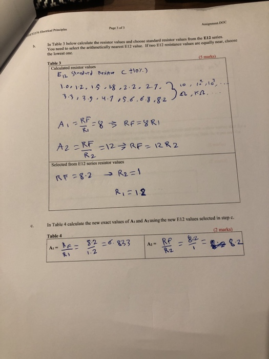

Page 3 of 3 22 lecical Principles b In Table 3 below calculate the resistor values and choose standard resistor values from the E12 series. You nced to select the arithmetically nearest E12 value. If two E12 resistance values are equally near, choose the lowest one. Table 3 Calculated resistor values 3.3 , 3., , ч.1 ,s,6,6 3-82 A,KA. RF - RF Selected from E12 series resistor values Rに1.2 In Table 4 calculate the new exact values of Ai and Az using the new E12 values selected in step c. c. Table 4 marks Az- 1.2
d. Calculate the output voltage Vut for the circuit if Vi-the 3rd last digit of your ID number (in mV)+500 mV V: = the 4th last digit of your ID number (in mV) + 100 mV Table 5 marks) c. Use MULTISIM or TINA eircuit simulation to create the op-amp circuit and print a clear screen shot for a fully labelled diagram of the simulated circuit with the voltmeters displays showing both the input and the output voltages. All voltage levels MUST be shown (8 marks) f Calculate Lo (2 marks) Table 6
Homework Answers


Add Answer to:
need help for d,e,f OP-Amp Circuit R-20k Fig 1 1. Design an operational amplifier circuit using an LM741 op-amp an...
An amplifier circuit is shown in Fig. 1b. The operational amplifier (op-amp) Ai can be assumed...
 An amplifier circuit is shown in Fig. 1b. The operational amplifier (op-amp) Ai can be assumed as ideal. The input impedance of this amplifier is 1M2. The gain of this amplifier is -100. R2 V R VVV 小小 Ri Fig. 1b (a) Show that 12 = (b) Find the expression of the voltage gain, Av, in terms Ri, R, R3 and R4. (c) Due to practical reasons, the maximum value to be used for the resistors is set at 1M2....
Problem 7 (CLO 3, 4, 11 - Ideal Op-Amps, Design): We will now design an Op-Amp...
 Problem 7 (CLO 3, 4, 11 - Ideal Op-Amps, Design): We will now design an Op-Amp circuit to perform the function where v1 - input voltage 1, input voltage 2, = input voltage 3, Vo = output voltage. It may be helpful to consult your recitation 6 (week 7) results as well as Table 4-3 for this problem. 7.a: Select an Op-Amp configuration for your design. Sketch the Op-Amp configuration with symbolic resistors (Rf, Ri, R2, etc) indicated. Do not...
A. (10 pts) Implement the voltage amplifier shown below using an ideal op amp circuit. You have o...
 a. (10 pts) Implement the voltage amplifier shown below using an ideal op amp circuit. You have one op amp available for this circuit, and a range of resistors with values from 1 kΩ to 100 ka. Draw the schematic of your op amp circuit, labeling resistor values. Make sure the gain, input resistance, and output resistance of your circuit matches the model in the schematic. R=012 *100v, RL 100 b. (5 pts) Your amplifier circuit should have a frequency...
63 k12 The Op Amp in the circuit shown in Fig. 1 is ideal, 30 k02...
 63 k12 The Op Amp in the circuit shown in Fig. 1 is ideal, 30 k02 12 V 12 k 12 - 12 V + a. Calculate vo when Vg equals 4 V. b. Specify the range of values of vg so that the Op Amp operates in a linear mode. c. Assume that Vg equals 2 V and that the 63 K12 resistor is replaced with a variable resistor. What value of the variable resistor will cause the Op...
4. Using resistor values in the 1 kOto 100 ㏀ range, design an op amp circuit...
 4. Using resistor values in the 1 kOto 100 ㏀ range, design an op amp circuit that has the following output voltage vout, where va, Vb, Ve and va are input voltages. Use as many op amps as you like
Figure 2 shows a multiple op-amp networks combined to produce a gain amplifier circuit. For the...
 Figure 2 shows a multiple op-amp networks combined to produce a gain amplifier circuit. For the given circuit: (i) Name all the type of op-amp circuits shown by Op-Amp 1 until Op-Amp 5. (ii) Calculate the output of each Op-Amp 1 until Op-Amp 4. Assume Vin = 10mV (iii) Determine the output voltage at the last Op-Amp 5. From this value, calculate the gain produced by this Op-Amp network in overall, by using Av=Vos / Vin equation. [10 Marks] CO3,...
1) Calculate the output voltage using the circuit of Fig for resistor components of value R=470Kohm...
 1) Calculate the output voltage using the circuit of Fig for resistor components of value R=470Kohm R=4.3 Kohm R=33Kohm & Rg=33Kohm (20) 2) Interpret the applications of op-Amp based on the ideal And Practical op-Amp characteristics (10)
Op Amp Integrators and Differentiators 1.) Design an op-amp circuit that acts as an integrator. Chose...
 Op Amp Integrators and Differentiators 1.) Design an op-amp circuit that acts as an integrator. Chose R and C values to give you a gain of 5 at f-1kHz Draw out the circuit and show the input and output, label all the pin numbers and show where the +-12 power supply connections for the chip are. Turn in the circuit diagram, carefully labelled 2.) Build your circuit and measure the gain as a function of frequency. Collect enough data to...
SOLVE ALL THE 3 questions using the properties of OPERATIONAL AMPLIFIER AND BJTs. Problem 1 10...
 SOLVE ALL THE 3 questions using the properties of
OPERATIONAL AMPLIFIER AND BJTs.
Problem 1 10 Marks A humidity sensor produces linear output voltage in the range of 0 V to 10 mV for humidity levels of 0 % to 100 % respectively. You are required to design the inverting op-amp circuit to achieve the voltage gain of 1000. Op-amp feed-back current should be 0.2 mA when op-amp output is at maximum. Solution: Problem 2 We discussed the summing circuit...
SOLVE ALL THE 3 questions using the properties of
OPERATIONAL AMPLIFIER AND BJTs.
Problem 1 10 Marks A humidity sensor produces linear output voltage in the range of 0 V to 10 mV for humidity levels of 0 % to 100 % respectively. You are required to design the inverting op-amp circuit to achieve the voltage gain of 1000. Op-amp feed-back current should be 0.2 mA when op-amp output is at maximum. Solution: Problem 2 We discussed the summing circuit...
5.20 The op amp in the circuit shown in Fig, P5.20 is ideal, Calculate v, when v, equals 3 V b) S...
 5.20 The op amp in the circuit shown in Fig, P5.20 is ideal, Calculate v, when v, equals 3 V b) Specify the range of values of vg so that the op amp operates in a linear mode. c) Assume that a's equals 5 V and that the 48n resistor is replaced with a variable resistor. What value of the variable resistor will cause the op amp to saturate? Figure P5.20 48 kΩ 15 kΩ 10 V 30 kΩ 10...
 An amplifier circuit is shown in Fig. 1b. The operational amplifier (op-amp) Ai can be assumed as ideal. The input impedance of this amplifier is 1M2. The gain of this amplifier is -100. R2 V R VVV 小小 Ri Fig. 1b (a) Show that 12 = (b) Find the expression of the voltage gain, Av, in terms Ri, R, R3 and R4. (c) Due to practical reasons, the maximum value to be used for the resistors is set at 1M2....
 Problem 7 (CLO 3, 4, 11 - Ideal Op-Amps, Design): We will now design an Op-Amp circuit to perform the function where v1 - input voltage 1, input voltage 2, = input voltage 3, Vo = output voltage. It may be helpful to consult your recitation 6 (week 7) results as well as Table 4-3 for this problem. 7.a: Select an Op-Amp configuration for your design. Sketch the Op-Amp configuration with symbolic resistors (Rf, Ri, R2, etc) indicated. Do not...
 a. (10 pts) Implement the voltage amplifier shown below using an ideal op amp circuit. You have one op amp available for this circuit, and a range of resistors with values from 1 kΩ to 100 ka. Draw the schematic of your op amp circuit, labeling resistor values. Make sure the gain, input resistance, and output resistance of your circuit matches the model in the schematic. R=012 *100v, RL 100 b. (5 pts) Your amplifier circuit should have a frequency...
 63 k12 The Op Amp in the circuit shown in Fig. 1 is ideal, 30 k02 12 V 12 k 12 - 12 V + a. Calculate vo when Vg equals 4 V. b. Specify the range of values of vg so that the Op Amp operates in a linear mode. c. Assume that Vg equals 2 V and that the 63 K12 resistor is replaced with a variable resistor. What value of the variable resistor will cause the Op...
 4. Using resistor values in the 1 kOto 100 ㏀ range, design an op amp circuit that has the following output voltage vout, where va, Vb, Ve and va are input voltages. Use as many op amps as you like
 Figure 2 shows a multiple op-amp networks combined to produce a gain amplifier circuit. For the given circuit: (i) Name all the type of op-amp circuits shown by Op-Amp 1 until Op-Amp 5. (ii) Calculate the output of each Op-Amp 1 until Op-Amp 4. Assume Vin = 10mV (iii) Determine the output voltage at the last Op-Amp 5. From this value, calculate the gain produced by this Op-Amp network in overall, by using Av=Vos / Vin equation. [10 Marks] CO3,...
 1) Calculate the output voltage using the circuit of Fig for resistor components of value R=470Kohm R=4.3 Kohm R=33Kohm & Rg=33Kohm (20) 2) Interpret the applications of op-Amp based on the ideal And Practical op-Amp characteristics (10)
 Op Amp Integrators and Differentiators 1.) Design an op-amp circuit that acts as an integrator. Chose R and C values to give you a gain of 5 at f-1kHz Draw out the circuit and show the input and output, label all the pin numbers and show where the +-12 power supply connections for the chip are. Turn in the circuit diagram, carefully labelled 2.) Build your circuit and measure the gain as a function of frequency. Collect enough data to...
 SOLVE ALL THE 3 questions using the properties of
OPERATIONAL AMPLIFIER AND BJTs.
Problem 1 10 Marks A humidity sensor produces linear output voltage in the range of 0 V to 10 mV for humidity levels of 0 % to 100 % respectively. You are required to design the inverting op-amp circuit to achieve the voltage gain of 1000. Op-amp feed-back current should be 0.2 mA when op-amp output is at maximum. Solution: Problem 2 We discussed the summing circuit...
SOLVE ALL THE 3 questions using the properties of
OPERATIONAL AMPLIFIER AND BJTs.
Problem 1 10 Marks A humidity sensor produces linear output voltage in the range of 0 V to 10 mV for humidity levels of 0 % to 100 % respectively. You are required to design the inverting op-amp circuit to achieve the voltage gain of 1000. Op-amp feed-back current should be 0.2 mA when op-amp output is at maximum. Solution: Problem 2 We discussed the summing circuit...
 5.20 The op amp in the circuit shown in Fig, P5.20 is ideal, Calculate v, when v, equals 3 V b) Specify the range of values of vg so that the op amp operates in a linear mode. c) Assume that a's equals 5 V and that the 48n resistor is replaced with a variable resistor. What value of the variable resistor will cause the op amp to saturate? Figure P5.20 48 kΩ 15 kΩ 10 V 30 kΩ 10...
Most questions answered within 3 hours.
-
Write the ionic equations for the first stage of salts
hydrolysis.
Anion, Cation?
Na2S
NiSO4
K2SO4...
asked 1 hour ago -
suppose there is a normally distributed population with a mean of
250 and a standard deviation...
asked 1 hour ago -
Question Three
Suppose you as project manager are using the Waterfall
development methodology on a large...
asked 2 hours ago -
Which statement is not true about welfare in Canada?
A.Benefits typically vary based on one's ability...
asked 3 hours ago -
Please help me with FLOWCHART and UML diagram for class,
thank you!
#include <iostream>
#include <fstream>...
asked 4 hours ago -
3. Describe the “logic circuit” of the Lac operon. Which
proteins are bound or not to...
asked 4 hours ago -
Ayesha’s adjusted gross income is $60,000 in 2019. She donated a
piece of artwork with a...
asked 4 hours ago -
For Dijkstra’s shortest path algorithm:
a. Give the Big-O time for Dijkstra’s shortest path algorithm
and...
asked 4 hours ago -
Phosphorus violates the 'octet rule' in biological molecules,
forming more covalent bonds than expected based on...
asked 4 hours ago -
A 1.3 eV electron has a 10-4 probability of tunneling
through a 2.4 eV potential barrier....
asked 4 hours ago -
What is the one ingredient that is common to being successful
with all stakeholders?
profit
trust...
asked 4 hours ago -
Write an assembly language 32 bit program that reads in lines of
text by a .txt...
asked 4 hours ago