
Homework Answers


Add Answer to:
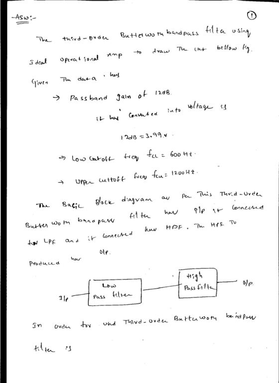
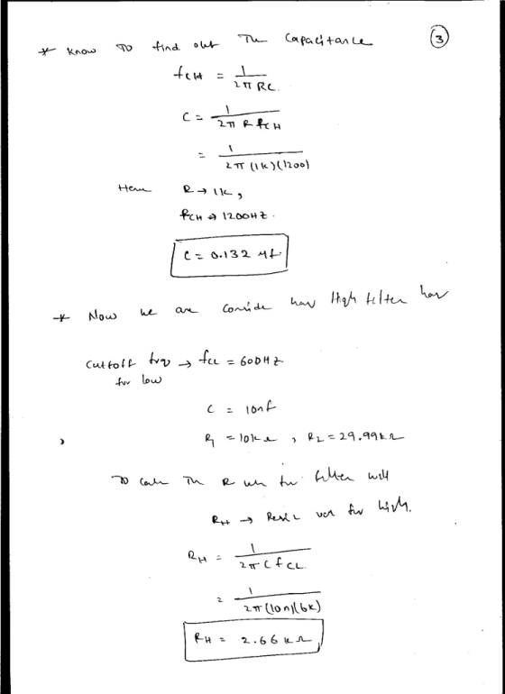
Problem 4. (6 marks) You are required to design a third-order Butterworth bandpass filter using ideal...
please need correct answer. I will upvote. Design a second-order digital bandpass Butterworth filter with a...
please need correct answer. I will upvote. Design a second-order digital bandpass Butterworth filter with a lower cutoff frequency of 1.9 kHz, an upper cutoff frequency 2.1 kHz, and a passband ripple of 3dB at a sampling frequency of 8,000 Hz. a. Determine the transfer function and difference equation. b. Use MATLAB to plot the magnitude and phase frequency respon
Design lowpass IIR filter with the following specifications: Filter order = 2, Butterworth type C...
Design lowpass IIR filter with the following specifications: Filter order = 2, Butterworth type Cut-off frequency=800 Hz Sampling rate =8000 Hz Design using the bilinear z-transform design method Print the lowpass IIR filter coefficients and plot the frequency responses using MATLAB. MATLAB>>freqz(bLP,aLP,512,8000); axis([0 4000 –40 1]); Label and print your graph. What is the filter gain at the cut-off frequency 800 Hz? What are the filter gains for the stopband at 2000 Hz and the passband at 50 Hz based...
4. We wish to design a digital bandpass filter from a second-order analog lowpass Butterworth filter...
 4. We wish to design a digital bandpass filter from a second-order analog lowpass Butterworth filter prototype using the bilinear transformation. The cutoff frequencies (measured at the half-power points) for the digital filter should lie at ω 5t/12 and ω-7t/12. The analog prototype is given by 1 s2+/2s+1 with the half-power point at 2 Determine the system function for the digital bandpass filter. a) b) Make the transfer from LPF to BPF in the analog domain Make the transfer from...
3. Design a bandpass FIR filter using Kaiser's formula for filter order, using Hamming window with...
 3. Design a bandpass FIR filter using Kaiser's formula for filter order, using Hamming window with the following specifications: the lower passband and stopband edge frequencies are fpi- 700 Hz, fs1 - 300 Hz, the upper passband and stopband edge frequencies fp2 - 2 kHz fs2 - 2400 Hz, the sampling frequency fs-10 kHz, and 6p-0.03, ando0.004.
Problem 2 a) Using 5 nF capacitors, design an active broad- band first-order bandreject filter with...
Problem 2 a) Using 5 nF capacitors, design an active broad- band first-order bandreject filter with a lower cutoff frequency of 1000 Hz, an upper cut-off frequency of 5000 Hz, and a pass band gain of 10dB. b) Draw the schematic diagram of the filter. c) Write the transfer function to find H(jωo), where ωo is the center frequency of the filter. d) What is the gain (in decibels) of the filer at the center frequency? e) Using Matlab make...
3.2 Simple Bandpass Filter Design The L-point averaging filter is a lowpass filter. Its passband width...
 3.2 Simple Bandpass Filter Design The L-point averaging filter is a lowpass filter. Its passband width is controlled by L, being inversely proportional to L. In fact, you can use the GUI altidemo to view the frequency response for different averagers and measure the passband widths. It is also possible to create a filter whose passband is centered around some frequency other than zero. One simple way to do this is to define the impulse response of an L-point FIR...
Problem 4 Use a 5 nF capacitor to design a series RLC bandpass filter. The center...
 Problem 4 Use a 5 nF capacitor to design a series RLC bandpass filter. The center frequency the filter is 8 kHz, and the quality factor is 1.5. Part A Specify the value of L. View Available Hint(s) EVO AQH vec ? L = 0.079 ml Submit Previous Answers * Incorrect; Try Again; 8 attempts remaining Part B Specify the value of R. 10 AEDIf vec ? R = k12 Submit Request Answer Problem 4 Use a 5 nF capacitor...
The MATLAB program below designs a lowpass filter for a passband edge frequency of 250Hz and...
 The MATLAB program below designs a lowpass filter for a passband edge frequency of 250Hz and a stopband edge of 350Hz. The sampling frequency is 2kHz. A Hamming window is used. (a) The program is on Webcampus. Run it and copy and paste the wvtool plots into Word. % FIR Filter Design (using wvtool) % Lowpass Design clear fpass 250; fstop 350; fs 2000; wp 2*pi* fpass/ fs; ws 2* pi fstop / fs; M=ceil(6.6 * pi / (ws-wp)) +...
Design a bandpass filter, using a cascade connection, to give a center frequency of 600 Hz,...
 Design a bandpass filter, using a cascade connection, to give a center frequency of 600 Hz, a bandwidth of 2 kHz, and a passband gain of 4. Use 250 nF capacitors. Part A Specify fal Express your answer to three significant figures and include the appropriate units. Part B Specify f2. Express your answer to three significant figures and include the appropriate units. Part C Specify RL Express your answer to three significant figures and include the appropriate units. Part...
Learning Goal: To analyze and design a passive, second-order bandpass filter using a series RLC circuit....
 Learning Goal: To analyze and design a passive, second-order bandpass filter using a series RLC circuit. A bandpass filter is needed for an equalizer, a device that allows one to select the level of amplification of sounds within a specific frequency band while not affecting the sounds outside that band. The filter should block frequencies lower than 1.8 kHz and have a resonant frequency of 5.4 kHz A 3.2 AF capacitor and any needed resistors and inductors are available to...
 4. We wish to design a digital bandpass filter from a second-order analog lowpass Butterworth filter prototype using the bilinear transformation. The cutoff frequencies (measured at the half-power points) for the digital filter should lie at ω 5t/12 and ω-7t/12. The analog prototype is given by 1 s2+/2s+1 with the half-power point at 2 Determine the system function for the digital bandpass filter. a) b) Make the transfer from LPF to BPF in the analog domain Make the transfer from...
 3. Design a bandpass FIR filter using Kaiser's formula for filter order, using Hamming window with the following specifications: the lower passband and stopband edge frequencies are fpi- 700 Hz, fs1 - 300 Hz, the upper passband and stopband edge frequencies fp2 - 2 kHz fs2 - 2400 Hz, the sampling frequency fs-10 kHz, and 6p-0.03, ando0.004.
 3.2 Simple Bandpass Filter Design The L-point averaging filter is a lowpass filter. Its passband width is controlled by L, being inversely proportional to L. In fact, you can use the GUI altidemo to view the frequency response for different averagers and measure the passband widths. It is also possible to create a filter whose passband is centered around some frequency other than zero. One simple way to do this is to define the impulse response of an L-point FIR...
 Problem 4 Use a 5 nF capacitor to design a series RLC bandpass filter. The center frequency the filter is 8 kHz, and the quality factor is 1.5. Part A Specify the value of L. View Available Hint(s) EVO AQH vec ? L = 0.079 ml Submit Previous Answers * Incorrect; Try Again; 8 attempts remaining Part B Specify the value of R. 10 AEDIf vec ? R = k12 Submit Request Answer Problem 4 Use a 5 nF capacitor...
 The MATLAB program below designs a lowpass filter for a passband edge frequency of 250Hz and a stopband edge of 350Hz. The sampling frequency is 2kHz. A Hamming window is used. (a) The program is on Webcampus. Run it and copy and paste the wvtool plots into Word. % FIR Filter Design (using wvtool) % Lowpass Design clear fpass 250; fstop 350; fs 2000; wp 2*pi* fpass/ fs; ws 2* pi fstop / fs; M=ceil(6.6 * pi / (ws-wp)) +...
 Design a bandpass filter, using a cascade connection, to give a center frequency of 600 Hz, a bandwidth of 2 kHz, and a passband gain of 4. Use 250 nF capacitors. Part A Specify fal Express your answer to three significant figures and include the appropriate units. Part B Specify f2. Express your answer to three significant figures and include the appropriate units. Part C Specify RL Express your answer to three significant figures and include the appropriate units. Part...
 Learning Goal: To analyze and design a passive, second-order bandpass filter using a series RLC circuit. A bandpass filter is needed for an equalizer, a device that allows one to select the level of amplification of sounds within a specific frequency band while not affecting the sounds outside that band. The filter should block frequencies lower than 1.8 kHz and have a resonant frequency of 5.4 kHz A 3.2 AF capacitor and any needed resistors and inductors are available to...
Most questions answered within 3 hours.
-
91. If the half – life of a sample of radioactive
material is 60 days, what...
asked 2 minutes ago -
White light (380nm-750nm) strikes a diffraction grating (420
lines/mm) at normal incidence. What is the highest-order...
asked 11 minutes ago -
1) Explain what is meant by a good being "excludable."?
2) Explain what is meant by...
asked 11 minutes ago -
I need help with this question:
Describe in detail at least two factors that stimulated American...
asked 18 minutes ago -
Calculate the Boyle temperature for helium assuming it follows
the Berthelot equation of state.
asked 18 minutes ago -
Summarize Strategic Corporate Social Responsibility, 4th edition
2017 book, chapter one and two.
asked 18 minutes ago -
1. If the standard deviations for return on stock A and stock B
are 28% and...
asked 34 minutes ago -
Please use python to explain.
Assume that the variables x and
y refer to strings. Write...
asked 40 minutes ago -
This table shows the US domestic demand and supply schedules
for oranges. Suppose the world price...
asked 40 minutes ago -
Please help me create a CLASS DIAGRAM for this code:
import pygame
from pygame.sprite import Sprite...
asked 42 minutes ago -
The Merriweather Printing Company is trying to decide on the
merits of constructing a new publishing...
asked 1 hour ago -
29) Insulin is a water-soluble hormone transported in the blood.
Which describes a likely way in...
asked 1 hour ago